Wire (2-Wire) Analog Input Devices – Advanced Automation
|
|
|
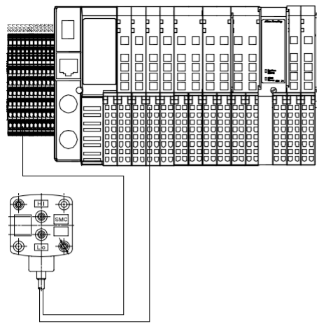
Connecting "loop-powered" analog input devices is usually straight-forward. They connect directly to the terminal blocks next to the IO rack in the control panel. These terminals contains the positive DC voltage reference wire connection for inputs. The PointIO rack contains the input modules used to send device status to the PLC, where the input signal is wired. Below is a typical differential pressure sensor field device wiring diagram. There are a wide variety of field sensors available on the market. Wiring is usually/can be polarity sensitive. Refer to the manufacturer’s installation instructions for specific wiring diagrams per your application. Use twisted-shielded cabling whenever possible, grounding only one end of the shield to earth ground.
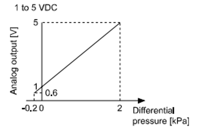
*Note – Inputs 0 – 3 can be used for analog inputs. Be sure to scale the analog input correctly in the programming according to the linear scale as shown above to the right. In this case, 1VDC (1000 digital) would equal -0.2 kPa and 5 vdc (5000 digital) would equal 2 kPa in the PLC logic. |