How Can We Help?
Wire (3-Wire) Digital Input Devices | Advanced Automation
|
|
|
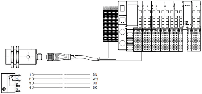
Connecting standard input devices is usually straight-forward. They connect directly to the terminal blocks next to the IO rack in the control panel. These terminals contains the positive DC voltage reference wire connection on the left, and the negative DC voltage reference wire connection on the right. The PointIO rack contains the input modules used to send device status to the PLC, where the input signal is wired. Below is a typical proximity sensor field device wiring diagram. There are a wide variety of field sensors available on the market. This is shown using PNP wiring scheme. Wiring is usually/can be polarity sensitive. Refer to the manufacturer’s installation instructions for specific wiring diagrams per your application.
|