PLC Programming
What is a PLC and PLC programming
A programmable logic controller (PLC) is a modular industrial computer used to automate the processes through real-time data collection. PLC programming is special computer code language used to control factory machines or processes. Bit Logic (1’s and 0’s) are what makes up the core foundation of the PLC code. A PLC monitors machinery through input devices, uses their vitals to make decisions and deploys control output to take actions based on the results of the program logic.
PLC programming is the real reason this industrial unit has become the standard system for control and automation in industries. Through PLCs, engineers don’t need to rewire every time a change occurs in the industrial process. They can simply program the PLCs again to serve the new purpose, saving time and resources!
Here are three major components you will find in a PLC
-
I/O modules
An I/O module in the PLC can be analog inputs, analog outputs, digital inputs, digital outputs, or a combination of the these. The I/O module is the bridge between I/O devices and the command unit. The input module collects information in the form of signals from actuators, sensors, switches, or push buttons. After processing according to the programmed logic of the PLC, the output modules send the signals to control devices like relays, valves, motor starters, alarms, and pumps.
-
A CPU module
Based on a microprocessor, the CPU module deals with all the processing and mathematical manipulation involved in the automation processes. It energizes or de-energizes the output in response to the input, manipulates memory locations, performs arithmetic and logical operations, transfers data between the ladder logic and itself, and executes the application program.
You will find two types of programs in a PLC CPU:
-
-
- Operating System –Supervisory set of permanent instructions loaded during manufacturing.
- Application Program –A customized program that determines the functionality of PLC on the basis of the customers’ demands.
-
-
Programming Device
The key component required for PLC programming is an external programming device. A PLC programming device can be a hand-held unit, a PC, or a desktop unit. Some of these require software, while others need a special interfacing card to interface with a PLC. An application program, generally in the form of ladder logic or C, is created in these devices and loaded into the PLC.
Once transferred, the programming device can connect to other PLCs to load other application software in their non-volatile memory. Hence, PLCs do not require a connection with a programming device to function.
The inception of PLC Programming
It was in 1968 that PLC (Programmable Logic Controller) was first invented before which industries and companies used relays to control their processes. PLC programming is basically giving the controller the required instructions in a form that the PLC can interpret. When General Motors designed specifications for a standard machine controller, they added some requirements to be met for the PLCs to be manufactured, which included modularity and expandability as well as its ability to be easily programmed and reprogrammed. The Bedford Associates produced the first PLC, named Modicon 084.
Although all computers use Boolean logic, the industrial engineers used ladder diagrams incorporated by the previously used relay systems. Richard E. Morley came up with the idea to use ladder logic in the control system, which made the PLC programming easier to understand for those engineers. Initially, there was no proper way to document the PLC programs, and so they needed to be hand-written or drawn using draft boards. Then in the 1980s, as computers became more common, PLC programs were made on them as they were much faster than previously used methods. And today, PCs have become a lot faster than in the previous decades, and PLC programming is done using them!
How does PLC programming work?
PLC programming usually refers to creating internal logic in a PLC, using a specific programming logic recognized by the IEC (International Electrotechnical Commission) standards.
There are two programs running in a PLC: the operating system and the user program.
The Operating System:
The operating system is the built-in PLC software that allows it to turn on, determine instruction sequences and implement all functions other than those related to control.
Important duties of a PLC OS are:
- Hot and Cold Start
- Interrupt Handling
- Executing Custom User Programs
- Interfacing with External Programmable Devices
- Dealing and Updating the I/O Device Data
The User Program:
The user program, added into the PLC according to the user requirements, uses an IEC standard programming language and implements control functions such as fault detection, temperature control, automatic filling system, stopping and starting escalators and elevators, etc.
The user program consists of multiple functions that allow the industry to dictate the output of PLC. Unlike the operating system, the user program is editable, making PLC a popular control device.
Professional PLC manufacturers have pre-designed user program logics and templates to decrease the overall deployment time. Once you make the order, they can make final changes to these pre-made implementations to create the final product.
You can stay in contact with your professional team to generate continuous upgrades and error handling according to your industry’s requirements. Also, every time you decide to introduce changes, your trusted team of professionals can make the necessary changes in the user program to complement the new processes.
Hence, you do not need to have your user program created from scratch every time a change arises in your factory or facility.
PLC Programming Languages:
Ladder logic revolutionized the field of PLC programming and hiked the popularity of Modicon 084, the first PLC in the 1960s. Morley’s genius idea dominated PLC programming for years until IEC was formed, and today, there are five internationally acceptable PLC programming languages under IEC61131-3. These languages can be divided into two categories:
- Textual Programming Languages
- Instructions List (IL)
- Structured List (SL)
- Graphical Programming Languages
- Ladder Diagram (LD)
- Sequential Flow Chart (SFC)
- Function Block Diagram (FBD)
Instructions List (IL):
Instructions list closely resembles assembly language and is commonly known as “Op-code.” Due to its textual nature, it consumes very little space. Hence, it works best with hand-held devices with limited memory but higher portability. You may recognize it by the symbols it uses, for instance, Input=I, Output=Q, Counter=C, and so on.
However, many programmers do not prefer Instructions Lists as it demands a large amount of time to detect bugs, maintenance and updates are harder due to their non-visual structure, and complex mathematical functions are hard to implement through them.
Some key features of the Instructions List are:
- Consists of lines of code, with each line representing exactly one operation
- Step-by-Step Layout
- Easier addition of simple mathematical functions
- Portability and multi-hardware support
- Faster execution in PLCs
- Editable without software, mouse, or laptop due to simple lines of code
- Suitable for simple and small PLC programs
Structured List (SL):
Structured language is a popular programming language that resembles high-level languages like PASCAL, C, and C++. It includes decision loops, case statements, IF-Then logic, and other features of high-level languages, making it one of the most powerful PLC programming languages to exist. Structured List is quickly being adopted out of all the IEC standard languages, and today hybrid languages involving SL and LD designs are also available.
Due to its textual nature, it requires proper structuring for easier maintenance, and it is not available on all makes and models of PLCs.
Some key features of Structured List are:
- Consists of decision loops, pointers, and case statements
- Indents, list spacing, and loop structure layout
- Quick addition of complex process logic
- Highly portable from one hardware to another
- Faster execution in PLCs than graphical languages
- Easily understandable for fresh graduates
- Suitable for large and complex PLC programs
Sequential Flow Chart (SFC):
Sequential flowchart is the simplest type of PLC programming language, consisting of only decision logics. It is similar in form and operation to the flowcharts programming students learn to make in their early days, with a start point, decision boxes, and actions boxes. Inside the action boxes, there is a repeatable set of instructions written in a language of programmers’ choice; for instance, a pick and drop task involves only one active set of instructions with exceptions.
SFC programming can lead to extremely long charts if the logic is complex and is not convertible into any other language.
Function Block Diagram (FBD):
Functional block is the second most popular programming language due to its graphical nature and easy-to-read structure. It resembles a ‘wiring structure,’ connected together in an easy-to-follow path.
Some key features of the Function Block Diagram are:
- Easiest to read
- Suitable for simple programs that implement digital logic
- Visually understandable for most viewers
- Requires large space
- Flow is hard to design and requires pre-planning
Ladder Logic (LD):
Ladder Logic is the most widely utilized PLC programming language all over the world, and rightly so. With its control-circuit-like structure, consisting of rungs and power rails on either side, this language was a convenient alternative to the relay logic of the 70s.
Ladder logic rungs have symbols representing the element connected to them, including contact symbols, comparisons, timer delays, output symbols, etc. As each input becomes ‘true,’ the outputs become activated.
Some key features of Ladder Logic are:
- Consists of symbols, rungs, and power-rails
- Wire-like graphical layout
- Implements timers, comparisons, basic math, trigonometry, and data analysis
- Suitable for both simple and complex programs
- Extensively large ladder handling is difficult
- It can be directly implemented without pre-planning
- Suitable for programmers and non-programmers alike
- Troubleshooting, bug handling, and maintenance are quick and simple
Why do you need effective PLC Programming?
PLCs can increase production, reduce workforce and duplication and save you from expensive shut-downs and equipment malfunctions. But for that, you need an effectively programmed PLC.
By getting your PLC programmed by skilled professionals, you can unlock its full potential. Otherwise, your investment in the automation system can go directly down the drain.
Here’s how effective PLC programming can help your business:
- Scalability: With effective PLC programming, you can future-proof your workplace and keep the options of scaling your equipment open.
- Integrating new equipment: Skilled programmers will reduce your expenses of reprogramming every time different system integration is introduced. You will be able to integrate new equipment without updating or renewing your PLC programs.
- High performance: Correct PLC programming means you are not underutilizing any of your machines and equipment’s capacity or capability.
- Enhanced Security: Your programming expert will ensure that your PLC-based system prevents your machines from malfunctioning, going out of sync, working beyond their capacity, or breaking down due to temperature hikes.
- Safety from Cyber Threats: Technological advancements have increased the threats of cyber-attacks and data theft. By employing a skilled set of professionals, you will be able to ensure that your systems are robust and resilient from external attacks.
How You Can Choose a Skilled PLC Programmer
Before hiring a programmer to program your PLC for it to work perfectly as you desire, you need to ensure that he has the following skills:
Knows Multiple Languages:
Ladder logic is the most widely used PLC programming language because of its graphical styles, but it isn’t the only one. The standard IEC 61131 has multiple PLC programming languages that can be used to program the PLC.
See which one suits your style and which one you are comfortable working with since the control of your entire system will depend on it. Since your PLC programmer will know multiple languages, he can guide you through all of them, which can help you with the selection process.
Can Incorporate a Modular Design:
Modularity in your PLC system will increase the system’s flexibility which will allow you to do multiple tasks easily, like adding I/O devices or organizing the system for better usability. Your PLC programmer should be able to know how to do that.
Configure Error Messages Properly:
Configuring error or fault messages across all devices helps to provide a standardized message system that will assist you in understanding any issue anywhere in the system. In case of improper configuration, you may not be able to understand what exactly the problem was, and so you might not be able to solve it!
Proper Coding and Commenting:
Once the code has been written, it may be needed to make some alterations in case of any required changes or some error. If the structure isn’t according to how you wanted it to be or has not been commented on properly, this process may be hideous and difficult. A PLC programmer that will code according to your preferred structure with proper commenting practices can prove to be highly beneficial in the long run.
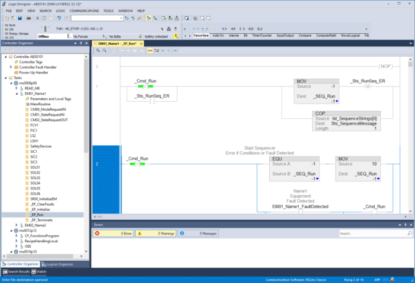
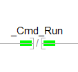
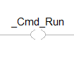
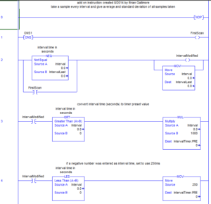
Simplest PLC Ladder Logic Elements
These are some, but not all, of the logic elements (also called programming instructions) found in PLC programs
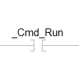
Much like a hardwired relay, this would act like a normally open contact. When the relay coil (OTE) is energized, this contact would close.
When the associated coil (OTE) is energized, this object will not show it closing the gap and connecting the wires, but rather it will be highlighted GREEN.
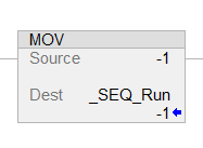
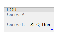
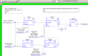
Advanced PLC Ladder Logic Elements:
These are some, but not all, of the more advanced PLC instructions
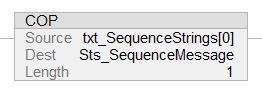
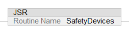
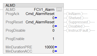
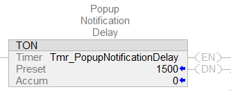
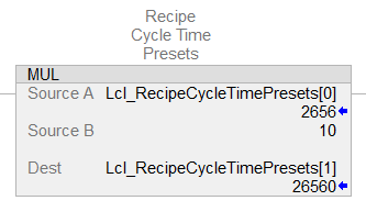
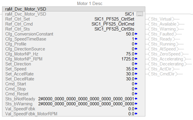
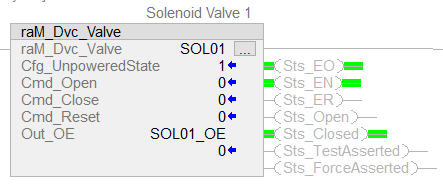
User-Created PLC Ladder Logic Elements:
These are some examples of user created PLC instructions
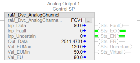
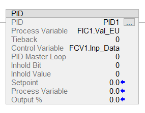
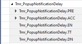
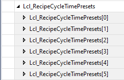
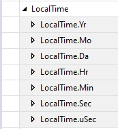
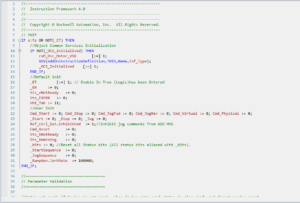
PLC Programming Tag Structures:
These are some examples of PLC tag structures
PLC Programming Languages:
These are four typical languages that can be used to program a PLC. They can all be used for any of these applications, but sometimes are better suited for what they were traditionally used to accomplish.
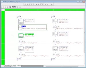
You can find the full instruction set for a PLC here. You can also find the user-created instructions here.
Contact us for PLC Programming!
If you are looking for skilled programmers to customize your PLC, you are at the right place. Automation Ready Panels provide remote PLC programming using pre-programmed templates, for continuous changes, or periodic improvements.
With our ability to provide online services, you don’t need to wait for our engineers to reach you. Get in touch, discuss your requirements and see your delivery being completed in record time!
Contact Automation Ready Panels today for a cost-effective, quick, and efficient solution to your automation problems.
SHOP NOW
-

Large Process Automation: Panelview 5000, ControlLogix 5580
$28,997.00 Select options -
Small Process Automation: Panelview 5000, ControlLogix 5580
$24,011.00 Select options -
Small Process Automation: ControlLogix 5580, UPS Battery Backup, Cellular Modem
$20,089.00 Select options -
Advanced Automation: Panelview 5000, Safety CompactLogix 5380
$12,547.00 Select options