What is PLC Ladder Logic and How Does it Work?
PLC Ladder logic is a programming language used with PLCs. Abbreviated as LD, it is also known as a ladder diagram, and it is one of the most widely-used visual programming languages for PLCs.
The ladder logic language is preferred over other programming languages because of its easy readability. It is much more visible and easier to learn this language due to the familiarity of symbols typically used on electrical schematics. A Programmable Logic Controller’s Ladder Code resembles electrical relay circuits in appearance. Engineers and maintenance personnel are already comfortable reading electrical schematics, so this makes it easier for these professionals to read this programming code as well.
In this article, you will learn everything you need to know about this programming language (ladder logic). After reading this, you can become familiar with PLC Programs and ladder logic in different PLC programming projects.

What is PLC Ladder Logic?
As mentioned above, ladder logic is a programming language, also called a ladder diagram or LD. It is used for programming a Programmable Logic Controller, often referred to as PLC. Being graphical, this PLC programming language defines logic operation using symbolic notation. The name Ladder Logic is used because it is built up with rungs of logic whose overall appearance resembles a ladder.
Although it is feasible to write complex computational code using LD, the primary use of this programming language is in “bit logic” operations. Simple bit logic is strongly used as the starting point of most PLC programs.
PLCOpen is the group/organization behind establishing ladder logic standards. Ladder logic is so much more than just a PLC programming language. It is also a benchmark programming language for PLCs. Being standardized means that it follows a set of rules (standard), IEC 61131-3. All that beginners should know is that an internationally recognized standard defines this programming language.
How Does Programmable Logic Control Ladder Work?
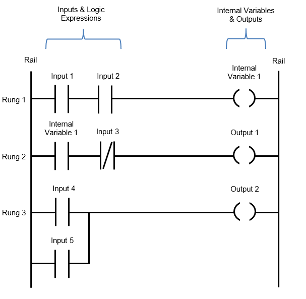
The three most fundamental ladder logic PLC programming instructions are Examine if Open (XIO), Examine if Closed (XIC), and Output Energize (OTE).
XIC (Examine If Closed):
When the bit is to 1/High, this input command will assess the condition to True by checking out the provided boolean bit. The command will evaluate the condition to False if the bit is set to 0/Low. If the condition is True, the rest of the ladder logic rung will be evaluated and executed.
XIO (Examine If Opened):
When the bit is to 0/Low, this input command will assess the condition to True by checking out the provided boolean bit. The command will evaluate the condition to False if the bit is set to 1/High. If the condition is True, the rest of the ladder logic rung will be evaluated and executed.
OTE (Output Energize):
When the bit is on 1/High, this input command will set it’s associated XIC to True. When the bit is on 0/Low, this input command will set it’s associated XIO to False

Basic Ladder Logic Rung Analysis:
Let’s have a look at these steps the PLC takes to evaluate the conditions of a rung of ladder logic:
Step 1.
The “current” beings flow from left to right.
Step 2.
When the hypothetical current comes into contact with an XIC instruction, it determines if the condition is 1/True or 0/False. The current will not flow to the rest of the elements in this rung if the XIC is False. It will allow current to pass if the XIC is True.
Step 3.
The current is then passed on to the next instruction. Step 2 is repeated until the rung is complete.
Step 4.
Lastly, the PLC advances to the next rung below and repeats these steps again.
The Bottom Line:
PLC Ladder logic is the most preferred programming language due to it’s graphical programming environment. It does not use complex text; instead, it uses a combination of graphic elements to the program. Symbols are the name for these visual elements.
These symbols resemble electrical symbols that have been used in electrical schematics for decades. Programmable logic controller’s ladder logic was designed with electricians, technicians, and electrical engineers in mind. It aims at making programming easier to learn, understand, and apply.
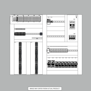
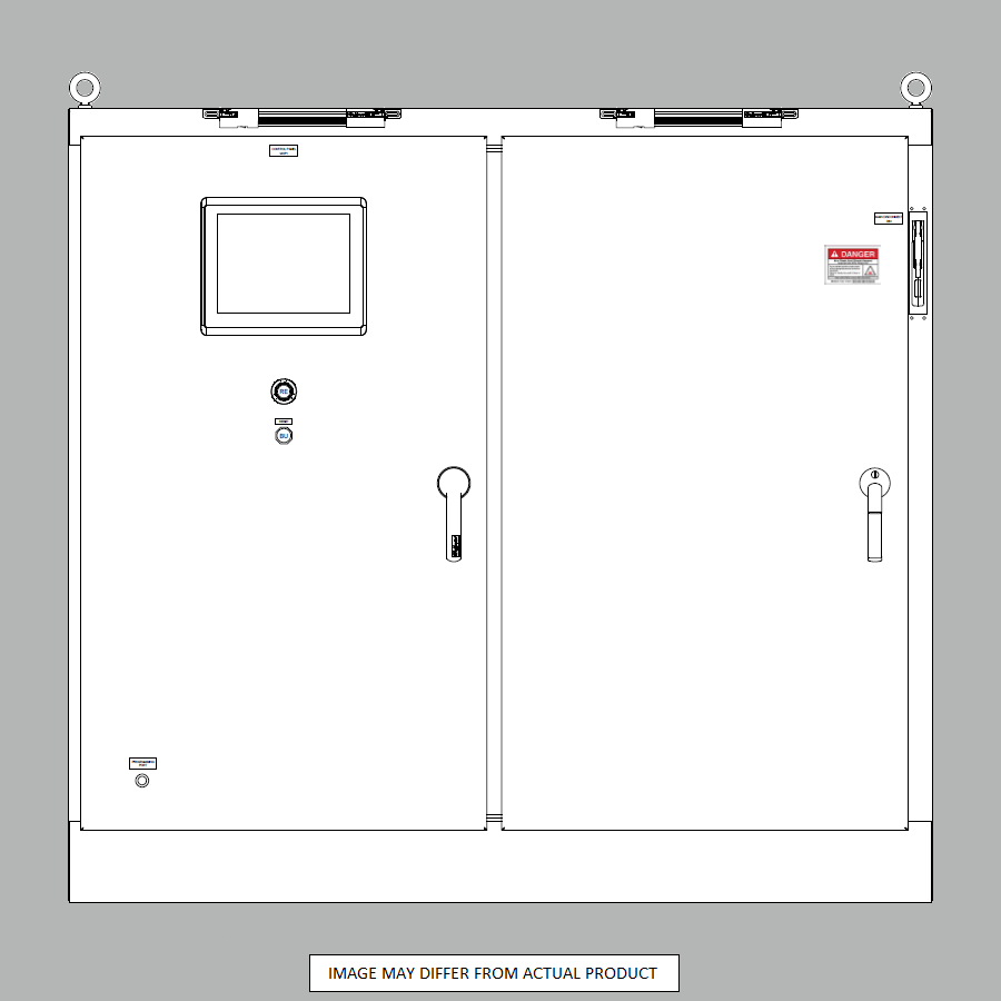
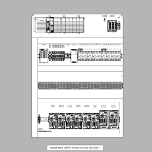
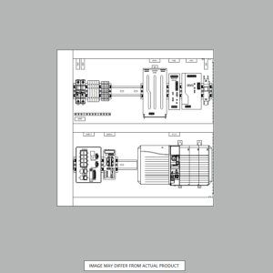
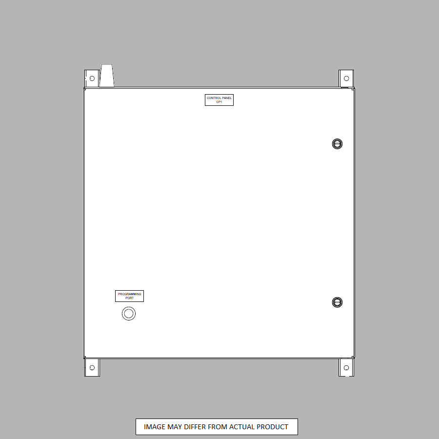
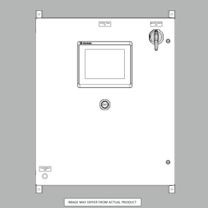
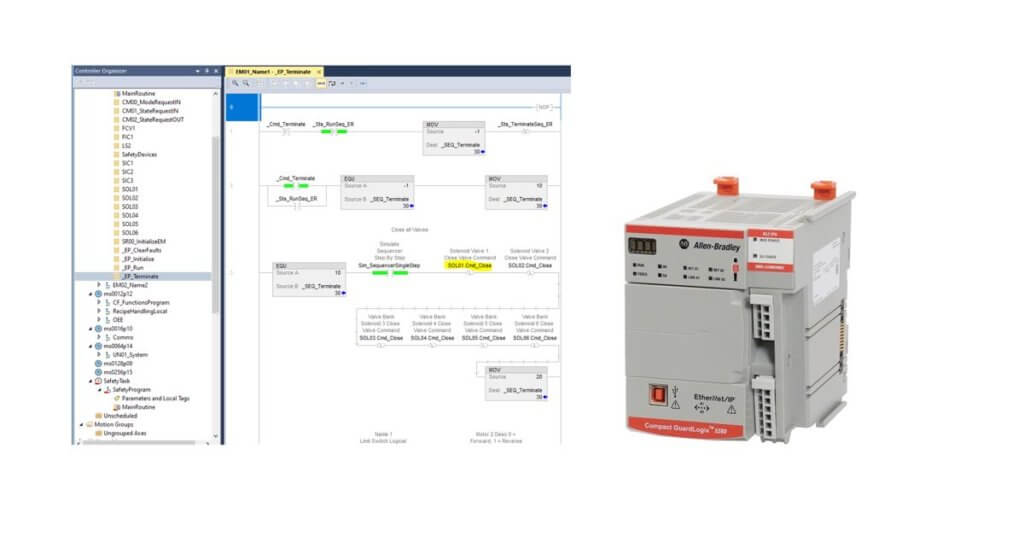
Automation Ready Panels sells standard and custom PLC control panels that are preprogrammed with advanced ladder logic already installed. Purchasing a panel online with us will give you a head start on learning ladder logic programming for your next project. It is 90% complete for you with rich logic examples programmed and ready to learn or use. Want to see what we offer? Shop Online Now!
Need to bounce your thoughts off an expert? Contact Us
SHOP NOW
-

Large Process Automation: Panelview 5000, ControlLogix 5580
$28,997.00 Select options -
Small Process Automation: Panelview 5000, ControlLogix 5580
$24,011.00 Select options -
Small Process Automation: ControlLogix 5580, UPS Battery Backup, Cellular Modem
$20,089.00 Select options -
Advanced Automation: Panelview 5000, Safety CompactLogix 5380
$12,547.00 Select options