How Can We Help?
Wire (2-Wire) Digital Input Devices | Basic Automation
|
|
|
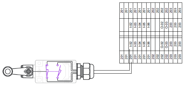
Connecting standard input devices is usually straight-forward. They connect directly to the dual level terminal blocks in the control panel. The bottom row contains the hot (or positive) reference wire connection. The top row is the input signal to the PLC that is the status of the input device. Below is a typical dry contact field device wiring diagram. There are a wide variety of field sensors available on the market. This is shown using PNP wiring scheme. Wiring is usually/can be polarity sensitive. Refer to the manufacturer’s installation instructions for specific wiring diagrams per your application.
|