How Can We Help?
Valve Connections and 2 Wire Digital Output Devices | Basic
|
|
|
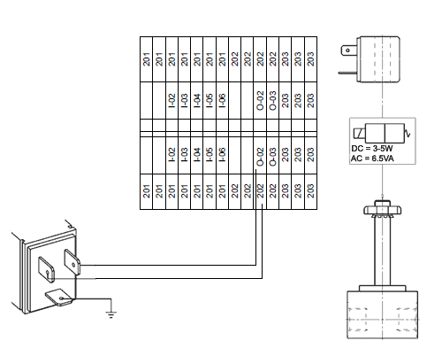
Connecting standard output devices is usually straight-forward. They connect directly to the dual level terminal blocks in the control panel. The bottom row contains the neutral (or negative) reference wire connection. The top row is the output signal from the PLC that actuates the output device. Below is a typical solenoid valve din connector wiring diagram. It should be similar for 24VDC and 120VAC. Refer to the manufacturer’s installation instructions for specific wiring diagrams per your application.
|