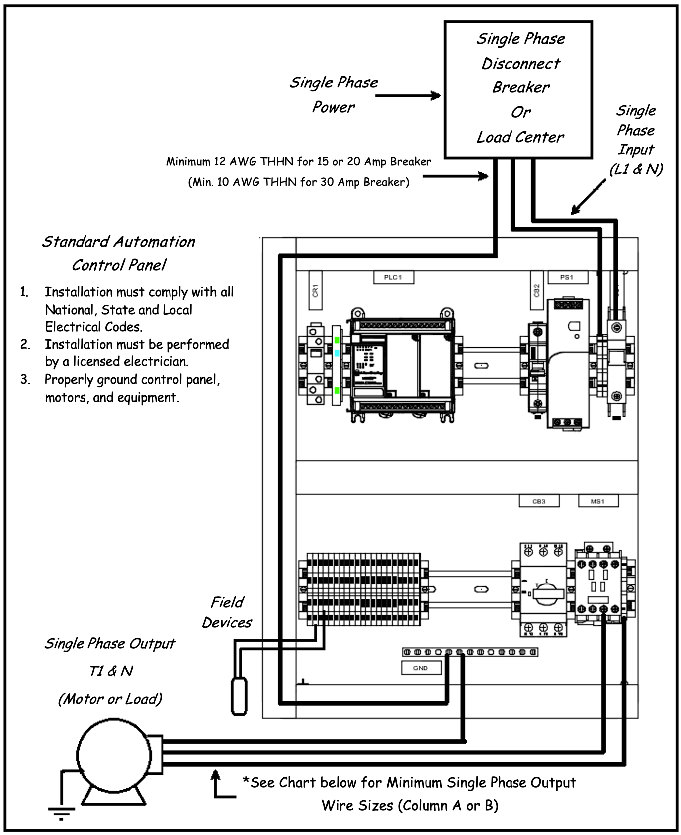
Typical 1 Phase Line Diagram
|
|
|
This is a typical line diagram for the Standard Automation single phase control panel design. The thick black lines coming in and out of the panel are the wiring that you will need to have a qualified electrician connect. There are two incoming (1-phase) power wires with a ground. There are motor leads (1-phase) for each motor with a ground. And there are power/signal wires (may require ground wire as well) for the sensors that your system uses, such as limit switches, level transmitters, etc. Each sensor will have specific wiring requirements, review the manufacturer cut sheets for recommending wiring of these sensors. See the diagram below for details:
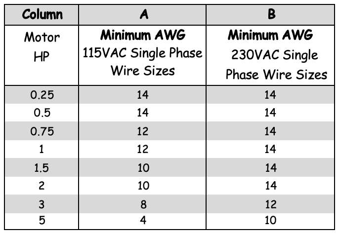
Below is a reference chart for the approximate minimum wire size required for motor connections (ensure you consult your federal, state, and local electrical codes to verify before using this chart). Risk of fire or shock can occur if wire with improperly sized wire or incorrect insulation. Use copper wire and minimum 14 gauge wire for all motor connections. Motor Wire Sizing Chart
Wire/Conductor Sizing: Wire sizing is extremely important in order that proper voltage may be maintained during motor start-up.
These wire recommendations are for wire runs of fifty (50) feet or less. Increase the wire size one (1) size for every additional fifty (50) foot run. Note – Wire recommendations are for copper wire.
|