Motor Connections
|
|
||
|
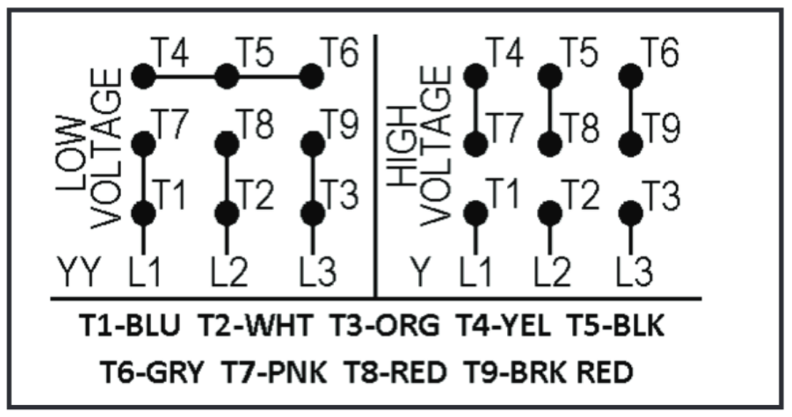
For 9 Lead Wire Motors
Output motor and load power connections are labeled T1, T2 and T3 of each motor starter or VFD.
Insulate all connections in the motor junction box with wire nuts, electrical tape and/or heat shrink tubing per national, state, or local code. Here is a typical dual voltage motor line diagram for reference (wire colors may vary per manufacturer):
Finally, properly ground motors to earth ground using a ring connector crimped to the ground wire. Always refer to the motor or load manufacturers wiring diagram for correct wiring. *Note – For 3 Phase Motors: Low voltage is 230 volts. High Voltage is 460VAC.
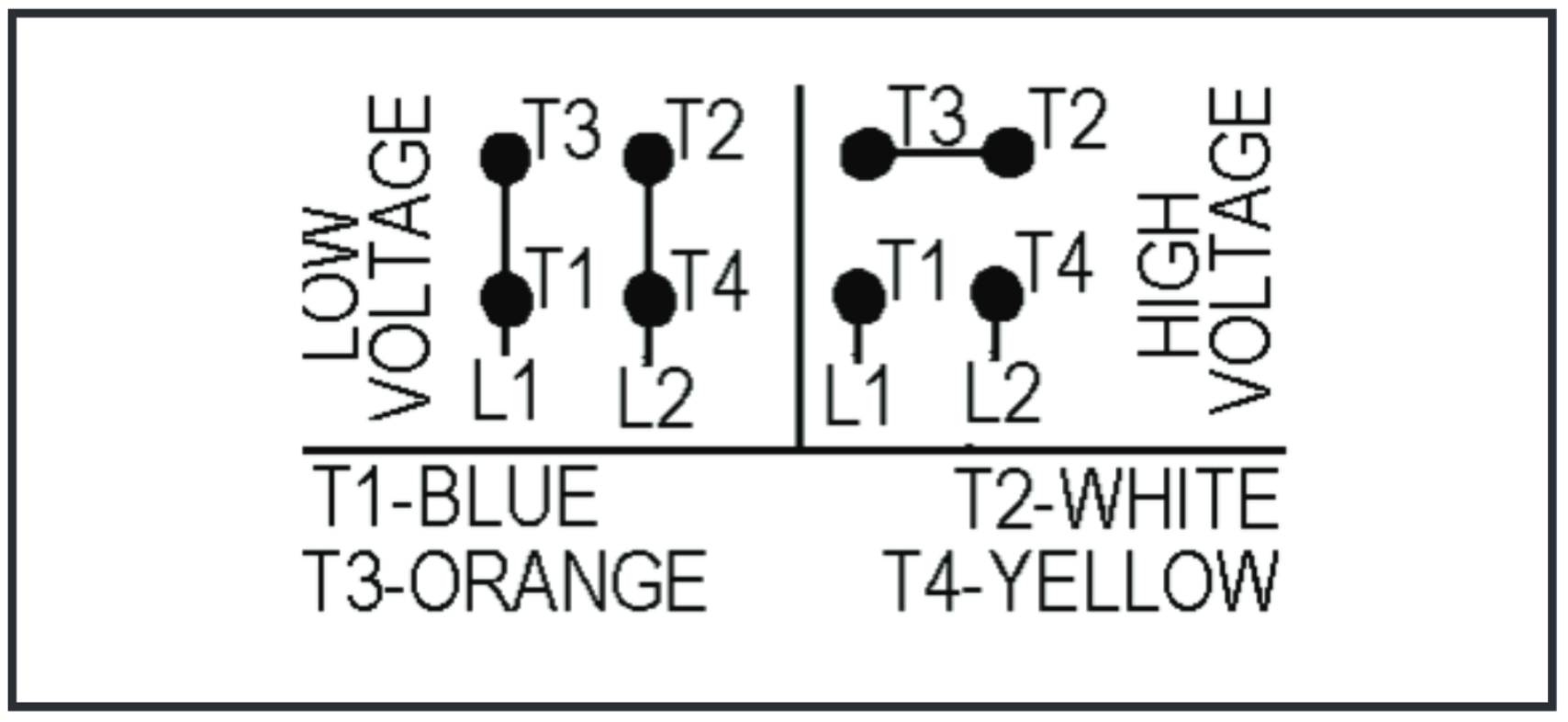
For 4 Lead Wire Motors
Insulate all connections in the motor junction box with wire nuts, electrical tape and/or heat shrink per national, state, or local code. Here is a typical dual voltage motor line diagram for reference (wire colors may vary per manufacturer):
Finally, properly ground motors to earth ground using a ring connector crimped to the ground wire. Always refer to the motor or load manufacturers wiring diagram for correct wiring. *Note – For 1 Phase Motors: Low voltage is 120 volts. High Voltage is 230VAC. If the motor is rotating in the wrong direction, swap any two of the three wiring motor leads to reverse rotation.
|
||