Ladder Diagrams and Logic: Simplifying PLC Programming
In the world of industrial automation, think of Programmable Logic Controllers (PLC) as the unseen heroes. They’re pivotal in streamlining complex electrical and mechanical tasks. And there’s one tool that’s been standing out in PLC programming: Ladder Diagrams and Logic.
Manufacturing processes have always been intricate. Controlling them efficiently demands a system that isn’t just powerful but also intuitive. Traditional methods can sometimes be difficult for those without a deep electrical background.
Enter Ladder Logic. Born in the late 1960s, it’s inspired by electrical relay logic. This means for those familiar with electrical systems, Ladder Logic feels like second nature. Yet, the true beauty lies in its graphical language – the Ladder Diagrams. These diagrams make complex processes look like simple steps on a ladder. They offer a bird’s-eye view of operations, ensuring every step is clear and orderly.
So why does Ladder Logic matter for your business? It simplifies the tough stuff. Troubleshooting becomes less of a headache. Communication between engineers is clearer. And the overall control of intricate systems? Much more efficient. When it comes to safety, monitoring, and precise control a priority, knowing Ladder Logic isn’t just helpful; it’s necessary. Dive into the basics, and you’re taking a significant leap towards optimal PLC programming.
Decoding PLC Programming: Your Key to Modern Automation
PLC programming is the skill of directing a machine (PLC) to handle automated jobs. Think of a PLC as a specialized computer. Unlike our everyday computers, a PLC’s main job is to run programs in a loop, consistently, and in a specific sequence.
Flashback to the late 1960s: the car industry had a challenge. They were using outdated relay-based systems and needed something smarter and more efficient. Enter PLC Programming. Over the years, it has been refined to be more compact, sturdier, and adaptable to different work settings.
Why should you care about PLC programming now? Here’s why:
- Flexibility & Compatibility: Not only does PLC programming give you endless ways to control machines, but it’s also in tune with today’s digital age.
- Widespread Use: From manufacturing plants to city infrastructures to the magic behind the scenes in theatres, PLC programming is everywhere. You can find it in assembly lines, factory robots, traffic lights, elevators, and even the cool lighting at amusement parks.
In essence, PLC programming isn’t just a tech term—it’s the foundation of many industries today. Understanding it equips you for a world that increasingly relies on smart automation.
Ladder Logic: A Glimpse Into Industrial Automation
Ladder Logic isn’t just a programming language; it’s a visual blueprint for industrial control. Used primarily within PLCs, Ladder Logic lets you direct machines or automate certain tasks.
Have you ever wondered about its name? Picture a ladder. The programming layout of Ladder Logic resembles this everyday object. It has two vertical sides, like the legs of a ladder, and multiple horizontal steps or “rungs.” Each of these rungs acts like a line of code, signaling a specific task or function.
Born in the early 1960s alongside the first PLCs, Ladder Logic was crafted to mirror electrical relay circuits. But as tech progressed, so did Ladder Logic. It now houses advanced features, including state transition diagrams and function block diagrams. Its visual simplicity and clarity are why, even today, with a plethora of PLC languages available, Ladder Logic stands tall. For those delving into automation and control systems, getting a grasp on Ladder Logic is pivotal.
Breaking Down Ladder Logic: The Core Components
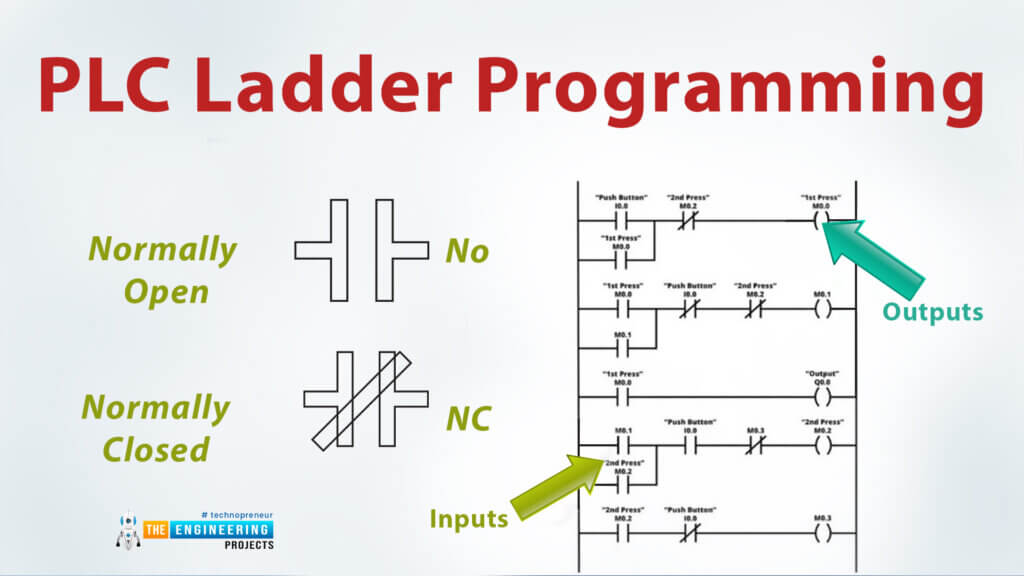
Ladder Logic is like the DNA of industrial control within programmable logic controllers (PLCs). At its heart, it’s a visual language with three key elements: contacts, coils, and blocks.
- Contacts: Think of contacts as the messengers. They show the PLC’s inputs, such as signals from switches or sensors. There are two types:
- Normally Open: Allows power to flow when closed.
- Normally Closed: Stops power when open.
- Coils: These are the action-takers, representing the PLC’s outputs like engines or pumps. They spring into action depending on the message from the contacts.
- Blocks: These are the brainy bits. Blocks deal with intricate tasks like timing or counting.
Imagine this: You press a button (a contact), which gets a conveyor belt (a coil) moving, but only for a set period (controlled by a block). Learning the basics can lead to more advanced automation in industries. By understanding these main parts, you can use Ladder Logic for accurate and efficient automation.
Deciphering Ladder Diagrams: A Guide to Visual PLC Programming
Ladder diagrams are the blueprints for programming, especially in PLCs. Why the name “ladder”? Simply put, they resemble one, featuring two vertical rails connected by horizontal rungs. These diagrams use symbols to show parts, visually telling the story of electrical circuits.
Their strength lies in their simplicity. In the industrial world, ladder diagrams are easier to use than many complicated software languages. They serve as a bridge, translating your commands into instructions for the PLC. This makes sure things like factory machines and energy plant systems run smoothly..
Here’s a brief on how you’d create a ladder diagram:
- Identify Inputs & Outputs: Start by pinpointing what the PLC needs to read (inputs) and what it controls (outputs).
- Draft the Logic: Formulate the initial control logic.
- Sketch the Diagram: Draw the components in a flow from left to right, showcasing the journey from PLC output back to its input.
- Forge the Connections: Create logical links between rungs, shaping the control process.
- Refine & Test: Regularly monitor and adjust your diagram to ensure peak performance.
For anyone navigating the world of PLC programming, mastering ladder diagrams is a game-changer. They’re not just tools; they’re the roadmap to effective automation.
Decoding Ladder Diagrams: A Beginner’s Guide to PLC Visualization
Navigating the world of programmable logic controllers (PLCs) requires a keen eye for ladder diagrams. Imagine these diagrams as a roadmap, helping you understand a system’s operation. Knowing how to read and interpret them is an indispensable skill.
Here’s your beginner’s guide:
- Get Familiar with Symbols: At the core of any ladder diagram are symbols. Each represents a component like switches, timers, or sensors. Every symbol has its distinct notation. Think of these as the “words” of the ladder diagram language.
- Follow the Flow: A ladder diagram showcases power flowing through paths, usually from left to right, across lines known as “rungs.” Understand the path, and you’ve got the basic structure down.
- Grasp the Logic: Beyond just symbols, you need to decipher the logic. This logic flow traces the power path, helping you fathom how one action follows another.
- Troubleshooting: With a clear understanding, you can spot when things go awry. Recognizing deviations from the norm becomes simpler, making problem-solving a breeze.
Whether you’re an engineer, technician, or a PLC enthusiast, mastering ladder diagrams ensures you’re equipped to handle and understand complex control systems. They’re not just drawings but windows into the heart of automation.
Ladder Logic in Action: How Industries Benefit
Ladder Logic, with its intuitive visual layout resembling electrical relay systems, is a pivotal tool for modern industry. It’s like the brain behind many automated processes, directing Programmable Logic Controllers (PLCs) in their tasks. But how does it play out in real-world settings?
- Conveyor Systems: Think of factories with belts moving items around. Ladder Logic dictates the direction of these belts. Need items sorted? Or handled a particular way? Ladder Logic is at the helm.
- Manufacturing Controls: From starting machinery to regulating speed or even activating emergency stops, Ladder Logic is the go-to. It ensures operations are safe and streamlined.
But here’s a closer look:
- Siemens Factory, Amberg, Germany: By embedding Ladder Logic in their PLCs, Siemens achieved a staggering 75% boost in operational efficiency. Their accuracy was unmatched, with errors dropping to a mere 12 out of a million.
- General Motors’ Paint Process: Painting cars got a revamp with Ladder Logic. The once time-consuming process of changing paint colors became quicker and more efficient, ensuring cars rolled off the production line faster and looking impeccable.
These examples aren’t mere industrial tales but success stories underlining Ladder Logic’s profound impact. Whether you’re in the industrial sector or simply curious, understanding the breadth of Ladder Logic’s applications can offer insights into the precision and efficiency of modern automation.
Ladder Diagrams and Logic: Strengths and Shortcomings
Ladder Logic, a popular choice in the realm of Programmable Logic Controller (PLC) programming, comes with its own set of perks and pitfalls. Let’s dissect both sides of this tool:
Advantages:
- Intuitive Design: Ladder Logic’s layout, reminiscent of electrical diagrams, translates complex operations into visually understandable sequences. It’s like reading a story instead of solving a puzzle.
- Universal Comprehension: One of its major strengths is its accessibility. Technicians and engineers, regardless of their programming prowess, find it easier to read and grasp Ladder Logic’s flow.
- Enhanced Productivity: By simplifying intricate tasks, Ladder Logic makes programming more efficient. This translates to quicker problem-solving and overall higher productivity.
Limitations:
- Limited Complexity Handling: While great for basic operations, Ladder Logic grapples with intricate mathematical functions and complex data types. It’s like using a basic calculator when you might need a scientific one.
- Verbose Coding: Its strength in readability is its weakness in brevity. Ladder Logic tends to expand, resulting in lengthy codes, especially for extensive projects.
- Not Always the Best Fit: For cutting-edge, intricate programming needs, other sophisticated PLC languages might be a better fit. Ladder Logic might shine in simplicity but can dim when faced with advanced challenges.
In summary, while Ladder Logic is undeniably a powerful tool in the PLC world, its utility varies based on the task at hand. It’s essential to weigh its benefits against its limitations to determine its aptness for a given project.
Boosting Your Proficiency in Ladder Diagrams, Logic and PLC Programming
The world of industrial automation thrives on tools like Programmable Logic Controller (PLC) and Ladder Logic programming. If you aspire to a future in robotics or electromechanical technology, improving your skills in these areas can pave your path to success.
Learning Resources:
- Online Courses: Platforms like Udemy and Coursera offer structured courses to get you started or deepen your understanding.
- Video Tutorials: Visual learners can benefit from instructional videos on YouTube, where experts break down complex concepts into digestible content.
- Guides and E-books: Dive deep into topics with comprehensive guides available across various platforms.
Skill-Enhancing Tips:
- Diversify Your Knowledge: Different PLC brands, from Siemens to Allen Bradley, have unique coding nuances. Familiarize yourself with these to be versatile.
- Simulation Software: Before diving into real-world scenarios, use simulators to safely practice and refine your programming skills.
- Community Engagement: Join online forums and PLC groups. Discussing, sharing, and even problem-solving in community spaces can offer fresh perspectives and insights.
- Stay Updated: The tech landscape constantly evolves. Make it a habit to keep up with the latest in PLC programming, be it new tools, methodologies, or best practices.
Remember that resources and tips give you a base, but regular practical, real-world use can refine your skills. By staying dedicated and always learning, you can become a leader in industrial automation.
Wrapping Up: The Power and Potential of Ladder Diagrams, Logic and PLCs
Simply put, mastering Ladder Logic and PLC programming isn’t just beneficial—it’s pivotal in today’s industrial automation landscape. Ladder Logic guides PLC programming by turning complex processes into visual steps.PLCs, acting on these cues, optimize and control industrial processes, ensuring industries operate at peak efficiency.
Peeking into the future, automation is set for a revolution. As IoT, AI, and machine learning advance, PLCs are set to change in amazing ways. We’re not just looking at simple automation; we’re on the brink of smart manufacturing, called Industry 4.0. In this imminent era, PLCs will be the linchpins, integrating seamlessly into these next-gen systems.
For those invested in this realm, the message is clear: PLC programming isn’t just a present-day tool; it’s the future’s foundation. To succeed in this changing field, keep learning and updated on new technology. The future beckons, and with Ladder Logic and PLCs in your arsenal, you’re poised to lead the charge.
-

Large Process Automation: Panelview 5000, ControlLogix 5580
$28,997.00 Select options -
Small Process Automation: Panelview 5000, ControlLogix 5580
$24,011.00 Select options -
Small Process Automation: ControlLogix 5580, UPS Battery Backup, Cellular Modem
$20,089.00 Select options -
Advanced Automation: Panelview 5000, Safety CompactLogix 5380
$12,547.00 Select options