What is a VFD? – How to use one in Applications
A Variable Frequency Drive (VFD), also known as an Variable Speed Drive (VSD) or Inverter, is an electronic device used to control the speed and torque of an electric motor by varying the frequency and voltage supplied to the motor. A VFD is commonly used in industrial applications to improve energy efficiency, control motor speed, and optimize processes. The components commonly used with a VFD include:
- VFD Unit: This is the main component of the system, responsible for controlling the motor’s speed and torque by adjusting the frequency and voltage of the output power. It typically consists of power electronics such as insulated gate bipolar transistors (IGBTs) and a microcontroller for signal processing.
- Power Input/Output Section: The VFD is connected to the power supply (AC mains) and the motor. It includes components like fuses, circuit breakers, and contactors to manage the power supply and protect the equipment from overloads and faults.
- DC Bus Capacitors: These capacitors store energy and help to smooth out voltage fluctuations in the DC bus of the VFD. They provide a stable DC voltage source for the inverter section.
- Rectifier: The rectifier converts the incoming AC power from the mains into DC power. It typically uses diodes to perform this conversion.
- DC Bus: The DC bus is the intermediate link between the rectifier and the inverter. It stores DC voltage that is used by the inverter to generate variable-frequency and variable-voltage output for the motor.
- Inverter Section: This section converts the DC voltage from the DC bus back into AC voltage but with variable frequency and voltage. This variable output is what allows the VFD to control the motor’s speed and torque.
- Microcontroller and Control Logic: A VFD has a microcontroller that processes input signals, such as desired speed and control commands, and generates the necessary control signals for the power electronics (IGBTs) in the inverter section. It implements algorithms to maintain the desired motor speed and manage other control functions.
- User Interface: VFDs often have a user interface, which could be a digital display, keypad, buttons, or a touchscreen. This interface allows users to configure parameters, set desired speeds, and monitor system status.
- Communication Interfaces: Some VFDs come with built-in communication interfaces such as Modbus, Profibus, Ethernet, etc. These interfaces enable the VFD to be integrated into larger control systems, allowing remote monitoring, data collection, and control.
- Braking Chopper (Optional): In some applications, a braking chopper (or dynamic braking resistor) is used to dissipate excess energy during deceleration or braking. It converts the excess energy into heat and helps to prevent overvoltage conditions.
- Filtering Components: To reduce electromagnetic interference (EMI) and radio frequency interference (RFI), additional filtering components like chokes and filters might be added to the VFD circuit.
- Temperature and Current Sensors: Sensors are often integrated to monitor the temperature and current levels of the motor and VFD components. This information is used for protection and maintenance purposes.
These components work together to provide precise control over the speed and torque of electric motors, making VFDs a versatile tool in various industrial and commercial applications.
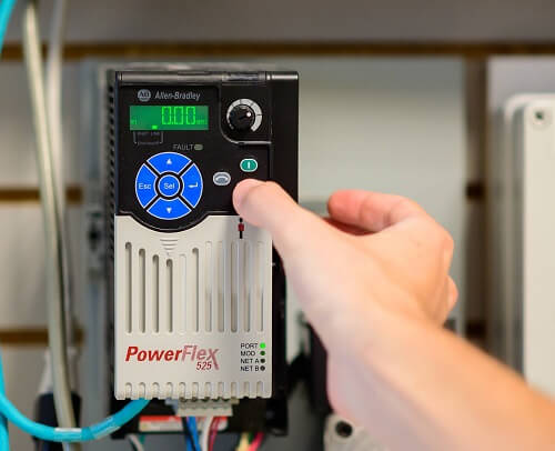
Allen-Bradley Powerflex 525 VFD
Understanding Line Filters and Load Filters
Line filters and load filters are both components used in conjunction with Variable Frequency Drives (VFD) to address different aspects of the electrical system. They are used to reduce noise, harmonics, and interference, but they are applied at different points within the system and target different issues.
Line Filter:
A line filter, also known as an input filter or power line filter, is typically placed on the input side of the VFD, between the power supply and the VFD itself. Its primary purpose is to filter out noise and disturbances generated by the VFD that could propagate back into the power supply network. The line filter helps to improve the power quality of the VFD’s input by reducing electromagnetic interference (EMI) and radio frequency interference (RFI). This helps prevent the VFD’s electrical noise from affecting other equipment connected to the same power source.
Key features of a line filter:
- Filters out noise and harmonics generated by the VFD before they reach the power supply.
- Reduces interference with other equipment sharing the same power network.
- Minimizes the risk of violating regulatory standards related to electromagnetic emissions.
- Enhances overall power quality on the supply side.
Load Filter:
A load filter, also referred to as an output filter or motor filter, is typically connected on the output side of the VFD, between the VFD and the motor it controls. Its primary purpose is to mitigate voltage spikes, harmonics, and electrical noise generated by the switching action of the VFD’s inverter. The load filter helps to smooth out the voltage waveform, reducing the stress on the motor and extending its lifespan. It also aids in preventing reflected waves that can occur due to the impedance of the motor and the cable connecting it to the VFD.
Key features of a load filter:
- Filters out voltage spikes, harmonics, and high-frequency noise generated by a VFD’s inverter.
- Helps to protect the motor by providing a cleaner and smoother voltage waveform.
- Reduces the risk of motor insulation breakdown due to high-frequency noise.
- Minimizes voltage reflections and cable stress.
In summary, a line filter is placed on the input side of the VFD to improve power quality and prevent the VFD’s noise from affecting the power supply network. On the other hand, a load filter is positioned on the output side of the VFD to protect the motor and mitigate voltage spikes and harmonics generated by the VFD inverter components. Both filters play distinct roles in optimizing the performance and reliability of the VFD system, but they address different aspects of noise reduction and interference mitigation.
What is a Braking Resistor?
A braking resistor, also known as a dynamic braking resistor or braking chopper resistor, is a component used in conjunction with a Variable Frequency Drive (VFD) system to dissipate excess energy during deceleration or braking of an electric motor. When a motor is decelerating or being actively braked, it acts as a generator, converting kinetic energy back into electrical energy. In a VFD system, this energy needs to be dissipated safely to prevent overvoltage conditions that could potentially damage the VFD and connected equipment.
Here’s how a braking resistor works within a VFD system:
- Motor Deceleration or Braking: During deceleration or braking, the motor acts as a generator, producing electrical energy as it slows down. In a VFD-controlled system, this generated energy can’t be simply fed back into the power supply.
- DC Bus Voltage Rise: The electrical energy generated by the motor’s deceleration or braking causes the DC bus voltage of the VFD to rise. If this rise is not controlled, it can lead to overvoltage conditions that might damage the VFD’s internal components.
- Braking Resistor: To prevent the DC bus voltage from rising excessively, a braking resistor is connected across the DC bus. When the voltage rises beyond a certain threshold, the VFD activates the braking resistor by connecting it to the DC bus. The resistor then absorbs and dissipates the excess energy as heat.
- Energy Dissipation: The braking resistor converts the excess electrical energy into heat energy, which is then radiated into the surrounding environment. The resistor’s resistance value is carefully chosen to provide effective energy dissipation.
- Voltage Regulation: By dissipating the excess energy as heat, the braking resistor prevents the DC bus voltage from exceeding safe levels, protecting the VFD from overvoltage damage.
Braking resistors are particularly useful in applications where the motor undergoes frequent deceleration or braking, such as in elevators, cranes, conveyors, and certain types of machinery. Without a braking resistor, the excess energy generated during these processes could lead to unstable VFD operation, component damage, or even complete shutdown of the system due to overvoltage conditions.
It’s important to note that some modern VFD systems may incorporate a built-in braking chopper circuit that converts the excess energy into heat internally, eliminating the need for an external braking resistor. However, the concept remains the same: managing and dissipating excess energy generated during motor deceleration or braking to ensure safe and stable operation of the VFD system.
How to Size the Incoming Circuit Breaker or Fuses Protecting the VFD, Motor, and Wire
Sizing a fuse or circuit breaker to protect a Variable Frequency Drive (VFD) involves selecting the appropriate current rating that can handle the potential fault currents and overloads that might occur in the system. This ensures the protection of the VFD, the connected motor, and the overall electrical system. Here’s a general process to help you size a fuse or circuit breaker for VFD protection:
- Gather Information:
- Obtain the VFD input current rating (typically listed on the VFD nameplate).
- Determine the full-load current (FLC) of the motor being controlled by the VFD. This information can also be found on the motor’s nameplate.
- Check the manufacturer’s documentation for any specific requirements regarding fuse or circuit breaker sizing for the VFD model you’re using.
- Select Protection Type:
- Decide whether you want to protect against short circuits and overloads or just overloads. Fuses and circuit breakers can provide both types of protection, but the sizing approach might differ slightly.
- Short Circuit Protection:
- For short circuit protection, you’ll need to calculate the prospective short-circuit current (PSC) available at the point of installation. This involves knowing the available fault current from the power supply network.
- The fuse or circuit breaker’s interrupting rating (AIC or IR) must be equal to or greater than the calculated PSC to ensure it can safely interrupt the fault current.
- Overload Protection:
- For overload protection, you’ll need to account for the VFD’s input current and the motor’s full-load current (FLC).
- The fuse or circuit breaker’s rating should be greater than the sum of the VFD’s input current and the motor’s FLC to prevent nuisance tripping during startup and normal operation.
- Derating and Sizing:
- Manufacturers often recommend derating the fuse or circuit breaker to ensure reliable operation. Derating factors may include ambient temperature, motor starting current, and duty cycle.
- Apply the derating factor to the calculated current to determine the final current rating for the fuse or circuit breaker.
- Select a Standard Size:
- Choose a fuse or circuit breaker with a current rating that’s equal to or slightly higher than the calculated and derated current.
- Use a standard size that’s readily available in the market.
- Check Coordination and Compatibility:
- Ensure that the selected fuse or circuit breaker is coordinated with upstream and downstream protection devices.
- Confirm that the selected protection device is compatible with the VFD and the motor.
- Consult Regulations and Standards:
- Check local electrical codes and standards for any specific requirements regarding protection devices and their sizing.
- VFD Installation and Testing:
- Follow manufacturer guidelines and electrical codes when installing the protection device.
- Test the system to ensure that the protection device operates as expected during both overload and short circuit scenarios.
Keep in mind that this process provides a general guideline for sizing fuses or circuit breakers for VFD protection. The specific requirements may vary depending on the VFD model, motor, application, and local electrical regulations. When in doubt, it’s recommended to consult with a qualified electrical engineer or professional who has experience in VFD installations and sizing protection devices.
Benefits of Using the Correct Wire and Cable Size and Type
Selecting the appropriate cable and wire for a Variable Frequency Drive (VFD) supply and motor connections is essential to ensure reliable and safe operation of the system. The choice of cable type, size, and length depends on factors such as the VFD’s power rating, motor power rating, installation environment, and electrical code requirements. Here are some guidelines to consider:
Supply Cable:
- Cable Type: Use shielded and properly grounded cable to reduce electromagnetic interference (EMI) and radio frequency interference (RFI). Common cable types include shielded power cables or multi-conductor cables.
- Cable Size: The cable size is determined by the VFD’s input current and the distance between the VFD and the power source. Consult the manufacturer’s documentation for recommended cable sizes based on the specific VFD model and the maximum allowable voltage drop.
- Voltage Rating: Choose a cable with a voltage rating suitable for the VFD’s input voltage.
- Length: Keep the cable length as short as possible to minimize voltage drop and EMI. Longer cable lengths can require larger cable sizes to compensate for voltage drop.
- Grounding: Follow proper grounding practices to ensure safety and reduce noise. Grounding the shield of the cable helps to manage EMI.
Motor Connection Cable:
- Cable Type: Again, use shielded and grounded cable for motor connections to reduce noise and interference. Suitable cables include shielded motor supply cables.
- Cable Size: The cable size is determined by the motor’s full-load current, voltage drop considerations, and distance between the VFD and the motor. Refer to the manufacturer’s recommendations and local electrical codes.
- Voltage Rating: Choose a cable with a voltage rating suitable for the motor’s voltage.
- Length: Keep the cable length between the VFD and the motor as short as possible to minimize voltage drop and EMI. Longer cable lengths may require larger cable sizes.
- Grounding: Properly ground the motor casing and the shield of the cable to manage noise and ensure safety.
- Motor Cable Insulation: Consider using cables with insulation suitable for the installation environment, such as cables with resistance to moisture, oil, or chemicals if required.
It’s important to note that cable sizing is a complex process that involves considering various factors such as derating for temperature, installation method, cable bundling, and other environmental conditions. Additionally, adhering to local electrical codes and regulations is crucial to ensure compliance and safety.
To determine the exact cable size and specifications for your specific application, it’s highly recommended to consult with a qualified electrical engineer who has experience in VFD installations. They can perform the necessary calculations and considerations to ensure proper cable selection and installation.
Is a VFD Rated Motor Required?
A Variable Frequency Drive (VFD) rated motor, also known as an “inverter-duty motor” or “VFD motor,” is a type of electric motor that is specifically designed to work optimally with a Variable Frequency Drive system. A VFD is used to control the speed and torque of electric motors by varying the frequency and voltage supplied to the motor. However, standard motors might not be suitable for use with a VFD due to the unique operating characteristics of these drives.
Here are some key characteristics of VFD rated motors:
- Insulation: VFD rated motors are designed with special insulation systems that can handle the high-frequency voltage spikes generated by the VFD. Standard motor insulation may break down due to the rapid voltage changes in VFD applications.
- Voltage and Frequency Range: VFD rated motors are designed to operate across a wide range of frequencies and voltages, matching the capabilities of the VFD. This ensures optimal performance and efficiency at various speed settings.
- Bearings: These motors often have bearings that are better suited to handle the increased loads and potentially higher shaft voltages caused by VFD-induced common mode currents.
- Cooling: VFD rated motors might have improved cooling designs to handle the potential increase in heat generation when operating at lower speeds or under varying loads.
- Oversizing Considerations: In some cases, VFD rated motors are oversized compared to standard motors to compensate for any potential current harmonics or increased heating effects at lower speeds.
- Harmonics and Noise: VFD motors are engineered to minimize the generation of electrical harmonics and mechanical vibrations, which can occur due to the variable voltage and frequency output of the VFD.
- Efficiency and Performance: VFD rated motors are optimized for efficiency and performance across a range of operating speeds. This ensures that the motor remains efficient even when operated at reduced speeds, which might be common in VFD applications.
When selecting a motor for use with a VFD, it’s important to consider the specifications provided by the motor manufacturer. Look for motors labeled as “inverter-duty,” “VFD rated,” or similar terminology. These motors are specifically designed to handle the unique challenges posed by a VFD and are more likely to provide reliable and efficient operation in such applications. Always follow the motor manufacturer’s guidelines and recommendations for proper installation, operation, and maintenance to ensure the longevity of both the motor and the VFD system.
Different Types of Network Communications
Variable Frequency Drives (VFD) are often equipped with various communication interfaces that allow them to be integrated into different types of networks and control systems. These communication interfaces enable remote monitoring, control, and data exchange, enhancing the functionality and flexibility of VFD systems. Some of the commonly available network options for a VFD includes:
- Modbus: Modbus is a widely used communication protocol in industrial automation. A VFD with Modbus capability can communicate with supervisory control and data acquisition (SCADA) systems, programmable logic controllers (PLCs), and other devices over RS-485 or Ethernet connections.
- Profibus: Profibus is a fieldbus protocol commonly used in process automation and manufacturing. A VFD supporting Profibus can communicate with other devices on the Profibus network, such as PLCs, sensors, and actuators.
- Ethernet/IP: Ethernet/IP is an industrial Ethernet protocol used for real-time control and information exchange. A VFD with Ethernet/IP capability can be integrated into Ethernet-based control networks, allowing seamless communication with other devices on the network.
- EtherCAT: EtherCAT (Ethernet for Control Automation Technology) is a high-performance industrial Ethernet protocol designed for real-time communication in motion control applications. A VFD supporting EtherCAT can be part of synchronized motion control systems.
- CANopen: CANopen is a communication protocol used in various industrial and automation applications. A VFD with CANopen support can communicate with other CANopen devices in the same network.
- Profinet: Profinet is an Ethernet-based communication protocol commonly used in automation systems. A VFD with Profinet support can be integrated into Profinet networks alongside other automation devices.
- DeviceNet: DeviceNet is a communication protocol used for connecting industrial devices in process automation and manufacturing. A VFD with DeviceNet capability can communicate with other DeviceNet devices, such as sensors and actuators.
- BACnet: BACnet is a protocol used in building automation and control systems. A VFD with BACnet compatibility can communicate with other BACnet devices, such as building management systems and HVAC controllers.
- Wireless Communication: Some VFDs also support wireless communication standards like Wi-Fi or Bluetooth, allowing for remote monitoring and control without the need for physical connections.
- Serial Communication: In addition to the network protocols mentioned above, A VFD often has standard serial communication interfaces like RS-232 or RS-485 that can be used for direct communication with other devices.
The choice of network for a VFD depends on the specific application, the existing control architecture, and the compatibility with other devices in the system. When selecting a VFD with communication capabilities, it’s important to ensure that the chosen protocol matches the requirements of your control system and that the necessary hardware and software support are available.
Understanding what Safe-Torque Off is and How it Protects People and Equipment
VFD Safe Torque Off (STO) is a safety feature commonly found in Variable Frequency Drives (VFD) and motor control systems. It is designed to ensure the rapid and safe cessation of torque production by the motor when the system enters a safety stop state. This feature is used to prevent unintended motor movement and to enhance the safety of personnel and equipment in various industrial applications.
Here’s how VFD Safe Torque Off works:
- Safety Stop Signal: When a safety stop condition is detected or triggered, such as an emergency stop button being pressed, a safety interlock being opened, or another safety event occurring, the VFD receives a signal to initiate a safety stop.
- STO Activation: Upon receiving the safety stop signal, the VFD activates the Safe Torque Off function. This function ensures that the VFD immediately cuts off power to the motor, effectively stopping the production of torque and bringing the motor to a safe and controlled stop.
- No Torque Output: While the VFD Safe Torque Off is active, the VFD ensures that no voltage or current is sent to the motor’s windings, preventing any chance of the motor generating torque and causing unintended motion.
- Safety Compliance: VFD Safe Torque Off is designed to meet specific safety standards and regulations, such as those outlined in the ISO 13849 and IEC 61508 standards. These standards provide guidelines for ensuring functional safety in machinery and systems.
- Maintaining Power: Although the torque production is stopped, the VFD may still maintain power to its control and communication circuits, allowing for safe monitoring, diagnostics, and other non-torque-related operations.
VFD Safe Torque Off is used in applications where there’s a need to quickly and safely bring the motor to a complete stop in emergency situations, such as when there’s a risk of injury to personnel or damage to equipment due to unintended motor movement. It is an essential safety feature in environments where people work in close proximity to machinery or where machinery needs to be stopped rapidly to prevent accidents.
It’s important to note that VFD Safe Torque Off is just one part of a comprehensive safety strategy. Other safety measures, such as proper guarding, emergency stop buttons, and risk assessments, should also be considered and implemented to create a safe work environment.
What is Volts per Hertz? And other VFD modes
“Volts per Hertz” (V/Hz) is a control method used in Variable Frequency Drives (VFD) to maintain a constant ratio of voltage to frequency as the motor’s speed changes. This control strategy is based on the principle that the ratio of voltage to frequency should remain relatively constant to ensure the motor’s magnetic flux remains constant, which prevents the motor from overheating and losing efficiency.
In the Volts per Hertz control mode:
- Voltage and Frequency Relationship: The VFD adjusts both the voltage and frequency output simultaneously, maintaining a constant V/Hz ratio. As the frequency is increased to speed up the motor, the voltage is also increased to maintain the desired ratio.
- Constant Torque Operation: The V/Hz control method is commonly used for applications that require constant torque operation, such as fans, pumps, conveyors, and many other industrial applications.
- Start-Up and Overload Performance: This method provides smooth acceleration and deceleration during start-up and prevents overloading the motor as its speed changes. However, this control strategy might have limitations at very low speeds, as the voltage might need to be boosted significantly to maintain the required magnetic flux.
- Simplicity: V/Hz control is relatively simple to implement and is suitable for a wide range of motor applications.
In addition to Volts per Hertz control, there are other control modes available in VFDs that cater to different motor and load characteristics. Some of these control modes include:
- Open-Loop V/Hz Control: This is the basic V/Hz control mode described above, where the VFD adjusts both voltage and frequency according to a predefined V/Hz ratio.
- Closed-Loop Vector Control (Flux Vector Control): Closed-loop vector control employs feedback from the motor to achieve more accurate control over speed, torque, and position. It can handle changing load conditions and allows for higher performance in terms of dynamic response and accuracy.
- Sensorless Vector Control: This control mode provides many benefits of closed-loop vector control without the need for an encoder or feedback device. It estimates motor parameters using algorithms and adjusts control parameters accordingly.
- Field-Oriented Control (FOC): FOC, also known as vector control, decouples the control of the motor’s flux and torque, providing precise control and high performance over a wide range of operating conditions. It’s often used for applications that require high efficiency and dynamic response.
- Direct Torque Control (DTC): DTC is a control strategy that directly controls torque and flux in the motor. It’s known for its rapid torque response and simplicity in implementation.
The selection of the control mode depends on the specific application requirements, motor type, load characteristics, and desired performance. More advanced control modes like vector control, FOC, and DTC provide enhanced performance but might require more complex setup and tuning compared to the simple V/Hz control.
Understanding the Basic Setup for a VFD
Setting up a Variable Frequency Drive (VFD) involves configuring various parameters to ensure proper operation and performance of the motor and the connected system. The exact parameters and values to be set can vary based on the VFD model, motor type, application, and specific requirements. However, here are some basic parameters that you’ll commonly need to set when setting up a VFD:
- Motor Data:
- Motor rated current: Input the motor’s rated current as specified on its nameplate.
- Motor rated voltage: Input the motor’s rated voltage.
- Motor rated frequency: Input the motor’s rated frequency (typically 50 Hz or 60 Hz).
- Motor poles: Specify the number of motor poles.
- Base Frequency:
- Set the base frequency to match the motor’s rated frequency (50 Hz or 60 Hz).
- Maximum Frequency:
- Set the maximum frequency to the desired operating range. Some motors and applications can handle frequencies higher than the standard base frequency.
- Acceleration and Deceleration Times:
- Set the time it takes for the motor to accelerate from zero speed to full speed and vice versa. These parameters control the ramp-up and ramp-down times.
- Voltage/Frequency Ratio (V/Hz):
- Set the V/Hz ratio based on the motor’s characteristics. For most applications, the V/Hz ratio remains constant for efficient operation.
- Control Mode:
- Choose the appropriate control mode for your application. Options may include open-loop V/Hz control, closed-loop vector control, sensorless vector control, etc.
- Overload Protection:
- Set the overload protection settings to prevent the motor from drawing excessive current during start-up or operation.
- Voltage Boost (Boost at Low Frequencies):
- Adjust the voltage boost settings to compensate for voltage drop at lower frequencies, ensuring sufficient motor torque.
- Current Limiting:
- Set the current limit to prevent the motor from drawing excessive current and potentially damaging itself.
- Braking and Deceleration:
- Configure the braking options if your system requires dynamic braking or if you’re using a braking resistor.
- Input and Output Configuration:
- Configure digital inputs and outputs for control signals, alarms, and interlocks.
- Communication Settings:
- Set up communication protocols if your VFD supports network connectivity (Modbus, Profibus, Ethernet/IP, etc.).
- Direction of Rotation:
- Define the direction of motor rotation (clockwise or counterclockwise).
- Motor Thermal Protection:
- Set up parameters for motor thermal protection based on the motor’s thermal characteristics.
- Fault Codes and Alarms:
- Configure fault codes and alarms to troubleshoot issues quickly.
- Start and Stop Modes:
- Choose start and stop modes, such as keypad control, external signals, or remote control.
- PID Control (if applicable):
- If using the VFD for closed-loop control with a process, configure PID control parameters.
- Motor Speed References:
- Set the sources for motor speed references (analog, digital, keypad, external signals).
- Energy-Saving Features:
- If available, enable energy-saving features like automatic output voltage reduction at lower loads.
- Motor Protection and Diagnostics:
- Configure protective features like phase loss protection, overcurrent protection, overvoltage protection, and undervoltage protection.
Remember that the above list provides a general idea of the parameters that need to be configured in a VFD. Always refer to the manufacturer’s documentation and guidelines specific to your VFD model and application for accurate parameter settings. Incorrect parameter settings can lead to improper motor operation, reduced efficiency, and potential damage to the motor and VFD. If you’re not familiar with VFD setup, consider consulting a qualified electrical engineer or technician for assistance.
How Close can a VFD be mounted to Other Devices?
The clearance required around a Variable Frequency Drive (VFD) for proper air flow depends on the VFD’s cooling method, the environment it’s installed in, and the manufacturer’s recommendations. Adequate clearance is important to ensure proper heat dissipation and prevent the VFD from overheating. Here are some general guidelines:
- Air-Cooled VFD:
- Air-cooled VFDs rely on the circulation of air to dissipate heat. It’s essential to provide sufficient clearance around the VFD to allow for proper air intake and exhaust.
- Typical clearance recommendations can range from 6 to 12 inches (15 to 30 cm) on all sides of the VFD.
- Ensure that the front, sides, and top of the VFD are clear of obstructions to allow air to flow freely.
- Ducted Airflow:
- Some VFDs allow for ducted airflow, where the VFD draws air from one location and exhausts it to another through a duct.
- In ducted installations, ensure that the ducts are properly designed and sized according to the manufacturer’s recommendations to maintain effective cooling.
- Filtered Air Intake:
- If the environment contains dust, contaminants, or other particles, ensure that the air intake is equipped with proper filters to prevent debris from entering the VFD and obstructing airflow.
- Heat Dissipation Ratings:
- Check the VFD datasheet or manual for the heat dissipation ratings. These ratings provide information about the VFD’s ability to dissipate heat in various conditions.
- Ventilation Requirements:
- Consider the ambient temperature of the installation environment. If the environment is hot or the VFD operates at high loads, additional ventilation might be needed.
- Local Regulations and Standards:
- Some industries or locations might have specific regulations or guidelines regarding equipment clearance for fire safety, accessibility, and maintenance. Ensure compliance with these regulations.
- Vertical Installation:
- If installing the VFD vertically, ensure that the clearance above and below the VFD is also maintained to facilitate proper airflow.
- Consult Manufacturer’s Recommendations:
- Always refer to the manufacturer’s documentation for specific clearance recommendations and installation guidelines for your VFD model.
Proper clearance and ventilation are crucial for the reliable and safe operation of a VFD. Insufficient airflow can lead to overheating, reduced efficiency, and even premature failure of the VFD. On the other hand, excessive clearance might not be necessary and could waste space. Therefore, it’s important to strike a balance by following the manufacturer’s guidelines and considering the specific environmental conditions in which the VFD will be installed.
How can a VFD Bypass Circuit be Used during VFD Repair?
A Variable Frequency Drive (VFD) bypass circuit, also known as a VFD bypass panel or bypass contactor, is a parallel arrangement of components that allows for manual or automatic transfer of power to and from a motor in cases where the VFD itself needs to be taken offline for maintenance, repair, or other reasons. The bypass circuit provides an alternative path for power to reach the motor, ensuring continued operation even when the VFD is not functioning.
The key components of a VFD bypass circuit typically include:
- Bypass Contactor: The bypass contactor is a heavy-duty electrical switch that connects the motor directly to the power supply when the VFD is bypassed. It allows power to flow to the motor without going through the VFD. The bypass contactor is controlled either manually or automatically, depending on the bypass configuration.
- Disconnect Switches: These are safety switches that isolate the VFD from the power supply and the motor. They ensure that power cannot be applied to both the VFD and the bypass circuit simultaneously.
- Start and Stop Controls: These are push buttons or switches that enable manual control of motor start and stop commands when using the bypass circuit.
- Overload Protection: The bypass circuit may include overload protection devices such as motor overload relays or thermal protection to prevent the motor from drawing excessive current and overheating.
- Bypass Timer: In some setups, a timer might be included to automatically return the system from bypass mode to VFD mode after a certain period. This helps prevent extended operation in bypass mode, which could lead to reduced energy efficiency.
The main purposes of a VFD bypass circuit are:
- Maintenance and Repair: When the VFD needs to be serviced or repaired, the bypass circuit allows the motor to continue running while the VFD is offline.
- Bypass in Case of VFD Failure: In the event of a VFD failure, the bypass circuit ensures that the motor can still operate, minimizing downtime.
- Startup and Commissioning: During initial setup and commissioning of the VFD system, the bypass circuit can be used to test the motor operation without using the VFD control.
It’s important to note that while a bypass circuit provides a convenient way to keep a motor running when the VFD is not operational, it should not be considered a permanent replacement for the VFD. The efficiency, control, and energy-saving benefits of using a VFD are lost when operating in bypass mode. The bypass circuit is mainly meant for temporary or emergency situations. Proper installation, labeling, and safety measures should be followed when designing and using a VFD bypass circuit.
Conclusion
VFDs (Variable Frequency Drives) are extremely beneficial devics to help you improve your machine, process, or factory automated systems. They have many technological advantages when searching for more understanding about downtime, effiencency, or saving costs on electricity usage.
Why Choose Automation Ready Panels for your next VFD Panel Project?
Our company utilizes Rockwell Automation’s Compact Low Voltage Powerflex 520 series and Standard Powerflex 750 series of VFDs in our products and solutions. These devices include state-of-the-art technologies to drive digital understanding of manufacturing processes and better safety for all people using this equipment.
Purchaing a VFD control panel from Automation Ready Panels gives you the following benefits:
- We design it for you, so you dont have to be an expert at the topics presented in this article.
- We supply it for you, completely built and tested, to the latest saftey and UL standards.
- They will show immediate payback for your operations in terms of utility costs, equipment wear, and/or flexibility of automation.
- Check out our VFD Panels here.
SHOP NOW
-

Large Process Automation: Panelview 5000, ControlLogix 5580
$21,389.00 Select options -
Small Process Automation: Panelview 5000, ControlLogix 5580
$17,999.00 Select options -
Small Process Automation: ControlLogix 5580, UPS Battery Backup, Cellular Modem
$16,999.00 Select options -
Advanced Automation: Panelview 5000, Safety CompactLogix 5380
$8,499.00 Select options