Powerflex 525 Parameters
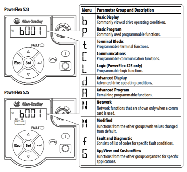
Powerflex 525 Parameters
Variable Frequency Drives (VFDs) are electronic devices that control the speed of an AC motor by adjusting the frequency of the electrical power supplied to the motor. Setting up Powerflex 525 parameters correctly is crucial to ensure that the motor runs smoothly and efficiently. In this article, we will outline the basic parameters that need to be set up in a VFD for optimal performance.
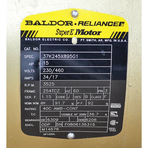
First, locate the motor nameplate. Lets assume the line voltage feeding the VFD is 460VAC, 3Ph, 60Hz. It is usually located on the outside of the motor housing and looks something like this:
Now, its time to set up the Powerflex 525 Parameters:
- Ensure the VFD is set to Factory Defaults as the starting point ( P053=2 FACTORY RESET)
- Voltage and Frequency: The voltage and frequency parameters are the most basic and important settings that need to be configured in a VFD. The voltage setting should match the voltage of the power supply, while the frequency setting should match the frequency of the power supply. These parameters determine the speed and torque of the motor, so it is important to set them correctly. In this case these are left at default values if a 460VAC, 3Ph, 60Hz model number is purchased. ( P031 MOTOR NP VOLTS, P032 MOTOR NP HERTZ) NOTE: NP is short for “Nameplate”
- Current Limit: The current limit is a safety feature that protects the motor and VFD from damage due to overloading. The current limit should be set to the nameplate current. ( P033=17 MOTOR OL CURRENT) The drive will fault on an F007 “Motor Overload” if the value of this parameter is exceeded by 150% for 60 s. NOTE: OL is short for “Overload”. Set ( P034=17 MOTOR NP FLA) to this value as well. NOTE: FLA is short for “Full-Load Amps”
- Operating Frequency Range: The range at which the VFD limits the motor speed. This can be set above motor nameplate frequency if desired to make the motor run faster in certain situations. Be careful not to set this too high as damage to the motor or equipment could occur. ( P043=0 MINIMUM FREQ, P044=60 MAXIMUM FREQ)
- Other Motor Data: Motor RPM sets the rated nameplate rpm of the motor. Used to calculate the rated slip of the motor. ( P036=3525 MOTOR NP RPM) NOTE: RPM is short for “Revolutions Per Minute”
- Speed Regulation: Speed regulation is the process of controlling the speed of the motor by adjusting the frequency of the power supply. The VFD should be programmed to regulate the speed of the motor based on the desired speed and torque. The control settings are:
- Set the start/stop control source
- Set ( P046=? START SOURCE 1) to “1” for VFD Keypad control, “2” for control via the hardwired terminals, and “5” for ethernet network control
- For Hardwired Control, set ( T062=48 2-WIRE FWD) (T063=50 2-WIRE REV) (T064=0 STANDARD 2-WIRE OPERATION)
- Set ( P046=? START SOURCE 1) to “1” for VFD Keypad control, “2” for control via the hardwired terminals, and “5” for ethernet network control
- Set the speed control source
- Set ( P047=? SPEED REFERENCE 1) to “1” for VFD Keypad potentiometer, “5” for 0-10VDC external signal, “6” for 4-20mA external signal, and “15” for ethernet network control
- Set the acceleration and deceleration settings
- Set ( P041=? ACCEL TIME 1) to the seconds the application requires for the motor to be at full speed from rest. Normal could potentially be 3.0s (customer application specific)
- Set ( P042=? DECEL TIME 1) to the seconds the application requires for the motor to return to rest from full speed. Normal could potentially be 3.0s (customer application specific)
- Set the start/stop control source
- Communication Parameters: Many VFDs have communication capabilities, such as Modbus, Profibus, or Ethernet, which allow the VFD to be connected to a control system or computer. The communication parameters should be set up correctly to ensure that the VFD can communicate with the control system or computer. For Ethernet/IP Communications:
- Set ( C128=1 EN ADDR SEL). This sets the communications settings to be pulled from the parameters set next
- Set ( C129=192, C130=168, C131=1, and C132=21 EN IP ADDR CFG). This sets the VFD to the IP address 192.168.1.21. Set to required IP address per application
- Set ( C133=255, C134=255, C135=255, and C136=0 EN SUBNET CFG). This sets the VFD to the subnet address 255.255.255.0. Set to required subnet address per application. This exact subnet is typical in 90% of cases.
- Set ( C137=192, C138=168, C139=1, and C140=1 EN GATEWAY CFG). This sets the VFD to the gateway IP address 192.168.1.1. Set to required gateway IP address per application. Most applications do not require a gateway. If using a managed network switch or remote modem, this would be the IP address of that device in order to route network traffic to other networks.
For all other parameters or Powerflex 525 setup/installation information, please consult the user manual found here.
In conclusion, setting up the Powerflex 525 paramters is crucial to ensure that the motor runs smoothly and efficiently. By configuring the voltage and frequency, current limit, speed regulation, communication parameters, overload protection, automatic start/stop, and automatic speed control, you can ensure that your Powerflex 525 and motor are functioning optimally and delivering the best performance.
Want to learn more about Powerflex 525 Parameters? Need to bounce your questions off an expert? Contact Us
SHOP NOW
-

Large Process Automation: Panelview 5000, ControlLogix 5580
$28,997.00 Select options -
Small Process Automation: Panelview 5000, ControlLogix 5580
$24,011.00 Select options -
Small Process Automation: ControlLogix 5580, UPS Battery Backup, Cellular Modem
$20,089.00 Select options -
Advanced Automation: Panelview 5000, Safety CompactLogix 5380
$12,547.00 Select options