What is an Analog Input?
What do we mean by a PLC Analog Input?
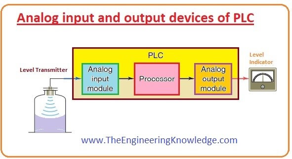
Continuous values, like temperatures and pressures, are analog values. We frequently think about them in digital terms, but at some point, we must translate them from the continuous world into a digital world. This is when a PLC analog input comes into play. Both milliampere current and low voltage signals are analog inputs to PLCs.
Why use an analog input and sensor over a digital input and sensor?
The data gathered from field input devices and applied to the PLC system is comprised of analog and digital PLC inputs. Weighing scales, oil pressure sensors, and temperature sensors are a few examples of real-world analog inputs to PLC systems utilized in industrial factories. Therefore, understanding the various PLC input types is a crucial precondition for factory automation.
There are two basic types of analog input signals: Voltage and Current. The manufacturer may offer the field device in one, either, or both of these signal types. Your job is to then specify the matching PLC input module that accepts one or both types.
Wiring a Current analog input can be divided into three types:
- 2-wire Analog Input
- 3-wire Analog Input
- 4-wire Analog Input
The manufacturer of the field device specifies how that specific device is wired. It is not usually a choice you get to make (unless you find a different manufacturer with the same type of field device that wires differently).
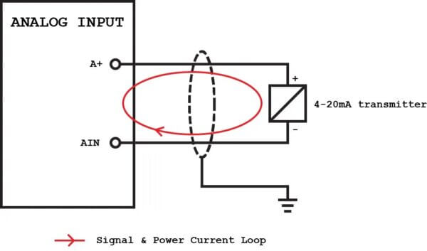
2-wire Analog Input
For the PLC to supply the current to the field device, a positive 24VDC terminal is used on the analog input module. In the image below, A+: Analog power supply wire that goes from A+ through the transmitter (field device) and back on another wire to AIN. The supply comes from A+, the transmitter restricts the current flow, and the analog current signal goes into AIN. In order to reduce external high voltage transients from scrabbling the analog signal, a twisted-pair and shielded cable is used to protect against those transients. Although there is some argument, it is considered best practice to only ground the cable shield to the electrical panel (and cut/tape it off at the field device) in order to not create a ground loop, causing other signal interference. Here is an IFM 2-wire pressure switch.
3-wire Analog Input
Here, the negative is shared by the supply and the signal in a three-wire current loop. The AGND and the power supply negative are the same reference signal, therefore wiring both of them are not necessary to wire, only one. The transmitter has 2 positive wires. One that goes to the power supply and the other that goes to AIN on the PLC. This is why it is called 3-wire analog input. Even if they share the ground, a 3-wire transmitter creates two loops. One for the supply, the other for the signal. It uses a twisted-pair shielded cable, same as the 2-wire analog input mentioned above. Here is an Allen-Bradley 3-wire flow switch.
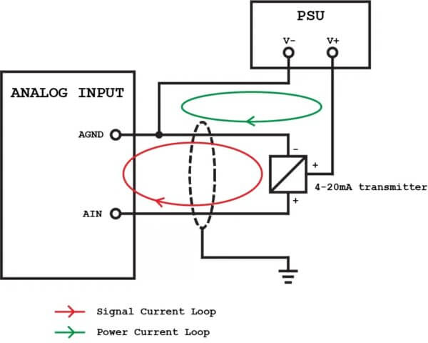
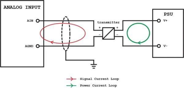
4-wire Analog Input
Since it isolates the supply from the signal, the 4-wire transmitter is very common. There can be 2 wires for the supply and 2 for the signal. The 4-wire transmitter needs an external power source. The total separation of supply and signal offered by a 4-wire transmitter is unquestionably its most significant benefit. They can be fully isolated or optoisolated so that disturbances in the supply should not affect the signal. Here is a Rosemount 4-wire flow meter transmitter.
Analog Signals
A PLC works with Boolean values of 0 and 1. This will work for digital. However, in the case of analog, if the electrical signal is 0-10 volts, we can translate it to binary numbers.
Representing an Analog Input with Binary Numbers
As mentioned before, a PLC works with the values 0 and 1 (the binary numbering system used by a PLC or any other computer).
Bits and Bytes
A binary number with only one digit is a bit. A binary number with many digits and can hold many whole numbers is multiple bytes. Each bit or byte can hold one or many 0 or 1s. If the number is signed with the initial bit, which can be either positive using a leading 0 or negative with a leading bit of 1.
A/D Converter
An A/D converter, also known as an analog to digital converter, processes the analog input signal before it enters the PLC. The PLC analog input card’s component that converts analog signals to digital signals.
Resolution of Analog Signal
The resolution is the number of bits you need to store an analog value. When working with analog signals in PLC programming, the resolution is crucial. The analog signal will be divided into a value. For instance, a 16 bit 2’s compliment integer would be between 0 and 32,767 when input into the analog input card. The resolution would be taking the maximum current signal or voltage signal dividing it into 32,767. For a 0-10 VDC signal, that would be 3,276 values per volt.
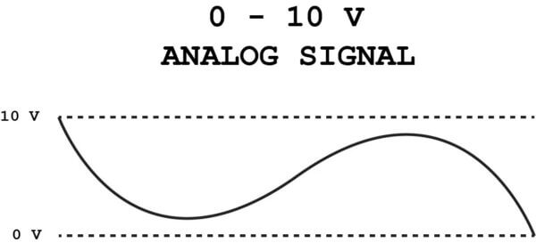
10 VDC Signal
0-10 VDC is an analog control signal used to control damper and valve actuators, VFD control, temperature, humidity, pressure sensors, and temperature reset. It is a commonly used control signal in the HVAC sector that is simple, trouble-free, and often used worldwide.
It is measured using a voltmeter capable of checking DC voltage.
Firstly, we must identify the wires’ signal (+) and the negative/common (-). Then set your meter to DC volts. Later, place the positive lead from the meter to the signal output terminal. Notice the output voltage.
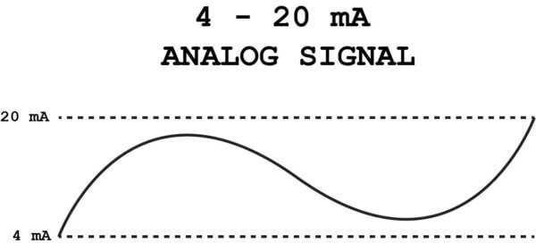
4–20 mA Signal
In the process automation industry, a point-to-point or multi-drop circuit is typically used to send signals from field instruments and sensors to a controller. It sends a 4 to 20 mA analog signal ranging from 0 to 100% of a process variable. In addition to powering the sensor transmitter on the same wire pair as a current loop signal, 4-20 mA also offers more immunity to interference than a voltage-based signal. A 0-20 mA signal is also offered, but has less advantage than a 4-20mA signal because if the signal goes dead (0 mA), a 4-20 mA signal would read very negative and would tell the PLC something is wrong with the signal.
Scaling
Scaling is the process of using computations to provide a signal, such as a process variable, voltage, or current output from a sensor, in a more manageable size and usable form in terms of engineering units, such as PSI, oF, or GPM to the operator in the control room. In data acquisition, there are three widely used methods: linear scaling, mapping scaling, and formula scaling.
Linear Scaling
Linear scaling employs the slope-intercept form ‘y = mx + b,’ where y is the output (also known as engineering units value), x is the input (voltages, milliamps, etc.), b is the y-intercept, and m is the slope. As already mentioned, linear scaling functions best with linear voltage or current outputs, where the minimum and maximum values correspond to particular values along with the sensor’s range.
How to troubleshoot and Analog Input using a digital multimeter
First, set the multimeter to measure DC voltage and plug the leads into the correct ports (refer to the manufacturer’s user manual for help). To check a 0-10 VDC signal, just hold the multimeter positive lead on the positive voltage wire. Then hold the multimeter negative lead on the negative voltage wire. The result will read on the multimeter LCD display.
To measure a 0-20 mA or 4-20 mA signal, set the multimeter to measure amps and plug the leads into the correct ports (refer to the manufacturer’s user manual for help). Unland the positive wire connecting the PLC analog input screw terminal to the field device. Now hold the multimeter positive lead on the analog input terminal you just unlanded the wire from. Then hold the multimeter negative lead on the loose positive voltage wire. The result will read on the multimeter LCD display.
Still confused about Analog Inputs? Need to bounce your questions off an expert? Contact Us
SHOP NOW
-

Large Process Automation: Panelview 5000, ControlLogix 5580
$28,997.00 Select options -
Small Process Automation: Panelview 5000, ControlLogix 5580
$24,011.00 Select options -
Small Process Automation: ControlLogix 5580, UPS Battery Backup, Cellular Modem
$20,089.00 Select options -
Advanced Automation: Panelview 5000, Safety CompactLogix 5380
$12,547.00 Select options