Hardware Block Diagram Explained
Imagine you’re trying to piece together a giant puzzle, but the pieces are a mix of various shapes and sizes. That’s what understanding the insides of electronic systems can feel like for many business leaders in manufacturing.
The problem is seeing how all parts of your production work together can be tough. When details get too technical, it’s easy to miss the big picture. That’s where the frustration kicks in. You want to ensure everything runs smoothly without getting bogged down by the nuts and bolts.
Now, think about having a clear, simple map showing exactly how your production line flows. That’s the hardware block diagram—it’s your high-level guide. It doesn’t show every wire or screw; instead, it shows you how the major parts connect and work together.
For anyone running a manufacturing business, this is your clarity. It’s like translating a foreign language into your mother tongue. The hardware block diagram helps you see the process without all the technical noise, allowing you to make smart decisions that can save time and money.
In short, it’s more than just a drawing. It’s the key to understanding your electronics easily, leading to a smoother operation and a better bottom line.
Detailed Description of Hardware Block Diagram
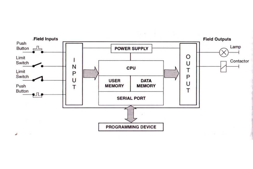
Think of a hardware block diagram as a map showing a computer system’s different parts. Like any map, it uses symbols to represent things. Here, squares or rectangles (“blocks”) stand for parts of the computer, like the brain (microprocessor) or the base (motherboard). Lines connect these blocks, showing how they talk to each other.
Some maps are simple, showing just the main roads, while others are detailed, with every street and alley. It’s the same with block diagrams. Some give you the big picture, like an architectural diagram showing the blueprint of the system. Others, like functional diagrams, focus on what the system does. Then, there are schematic diagrams, which are like a detailed street map for data, showing where it goes and how it flows between the blocks.
The arrows on these diagrams are like one-way streets, directing the flow of information. They show how one part sends signals to another, controlling or affecting how it works. This makes it easy for anyone—whether it’s a tech expert or someone new to electronics—to see how the whole system fits together and works as a team.
The Process of Creating a Hardware Block Diagram
Building a hardware block diagram is like drawing a family tree for a computer system. Here’s how it’s done, step by step.
First, figure out who’s in the family. That means picking out all the parts you need, like the brain of the computer (the central processing unit), the short-term memory (RAM), and the places where the computer gets information (inputs) or sends it out (outputs).
Next, sketch out where everyone stands in the tree. You’ll want to arrange these parts to show who talks to whom clearly and simply. The goal is to make it look neat and make sense at a glance.
Then, you draw the lines that connect them. These aren’t just random lines; they’re like the conversations between family members. They show who’s sending information, who’s taking orders, and who’s powering who.
Last but not least, you name everyone and every line. This means labeling each part and connection so anyone looking at the diagram knows exactly what each thing is and what it does. The end result? A family portrait that clearly shows how a computer’s hardware pieces work together as one big, happy family.
Importance of Hardware Block Diagram in Designing Electronic Systems
Hardware block diagrams are the secret weapon for designing electronic systems. They’re like the “X marks the spot” on a treasure map, guiding you to understand complicated electronic treasures.
At point A, they’re a game-changer. They break down and show the relationships in the system so that anyone can grasp how the system works. It’s about turning complex tech language into an easy-to-follow story.
Then, at point B, they’re like having a crystal ball. They help spot problems before they become big, expensive headaches. This foresight saves time and money, which is gold in the electronics design world.
Regarding teamwork (Point C), these diagrams are the ultimate team players. They make sure everyone—from engineers to project managers—speaks the same language, clearly and loudly. This way, no detail is lost in translation, avoiding mix-ups.
Lastly, at point D, they’re like a trusty guidebook for the lifetime of the system. They make troubleshooting a breeze by laying out the system so you can pinpoint issues and fix them quickly.
In a nutshell, hardware block diagrams aren’t just useful; they’re a vital tool in crafting electronic systems that are smart, cost-effective, and easy to manage.
Examples of Hardware Block Diagrams
Hardware block diagrams are like simple maps for electronic devices. Let’s look at a couple of easy examples.
Think of a basic home computer. In its block diagram, you’d see a few main parts: the CPU (it’s like the computer’s brain), the memory (where the computer keeps the information it needs), and places where you plug in things like the keyboard or mouse (these are the computer’s ways of getting your instructions and showing you stuff). They’re drawn as blocks, with lines showing how they work together.
Imagine the inside of a video game console if we go up a level. Its block diagram has more parts, like the parts that do the math for the games, the parts that store game data, and the parts that send the video to your TV. The diagram shows how all these parts talk to each other to make your games work.
Now, let’s think about a smartphone. An engineer’s block diagram for a phone includes the chip that runs apps, the space where photos and apps are stored, the camera, and the screen. The diagram helps the engineer see how everything connects, making building and fixing the phone easier if something goes wrong.
In short, hardware block diagrams are like the instructions you get with flat-pack furniture, showing you how everything fits together to work properly.
Software Tools for Creating Hardware Block Diagrams
Need to create a map for an electronic system? You can use different software tools, whether you’re watching your budget or need something advanced.
For starters, Draw.io and Lucidchart are free and easy. They have all the basic shapes and lines you’ll need. You can draw simple or somewhat complex diagrams without paying anything.
If you need more professional tools, Microsoft Visio and AutoCAD are like the deluxe paint kits for engineers. Visio is great if you already use Microsoft Office, while AutoCAD is for when every little detail is super important, like in building plans.
So, what should you use? It depends on how detailed your diagram needs to be and how much you want to spend. Free tools are good for most tasks. But if you need lots of detail, paying for Visio or AutoCAD might be worth it. The main thing is to pick the tool that’s right for your project.
Tips and Tricks for Drafting Efficient Hardware Block Diagrams
Drafting a hardware block diagram effectively is about making a complex system easy to understand. Here are some tips to help you draw a clear and useful diagram:
- Keep it simple. Don’t crowd your diagram with too much detail. Stick to the essentials to keep the overview understandable.
- Stick to the standards. Use well-known symbols and shapes that most people will recognize. If you use colors, make sure they follow a standard color-coding system to avoid confusion.
- Scale it right. When drawing different parts, use a consistent scale. This helps show the importance or size of each part in relation to others.
- Label clearly. Every connection should have a clear label. If there’s a direction to the flow of information, make sure arrows or indicators are easy to read and unambiguous.
- Double-check. Always compare your diagram to the real system to ensure accuracy. Leaving out a part or drawing something wrong can lead to misunderstandings.
- Think of your audience. Use simple terms and avoid technical jargon. When you have to use specific terms, include a legend to explain them.
- Flow logically. Arrange your diagram so that it’s easy to follow the path from one component to the next, like following steps in a recipe.
Remember, the main goal of a hardware block diagram is to communicate how a system is built and works. Focus on making your diagram both precise and easy to digest, whether for experts or newcomers.
Conclusion
To wrap things up, think of function block diagrams and PLC programming as the building blocks of electronic engineering. A function block diagram is your visual guide, laying out the flow and connections of a system for easy troubleshooting and design tweaks. Meanwhile, PLC programming automates machinery, letting it run on its own without constant human guidance.
Together, these tools are all about making electronics better and smarter. They help teams communicate clearly and work efficiently. Our main takeaway? Understanding hardware block diagrams is key to smooth teamwork and successful projects.
So, I encourage you to take what you’ve learned about diagrams and PLCs and put it to work. Being skilled at reading a function block diagram and programming a PLC is a true mark of expertise in electronics. These abilities are more than just impressive – they’re essential for solving problems and ensuring project success.
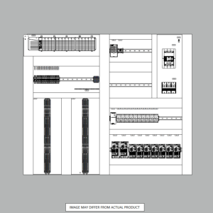
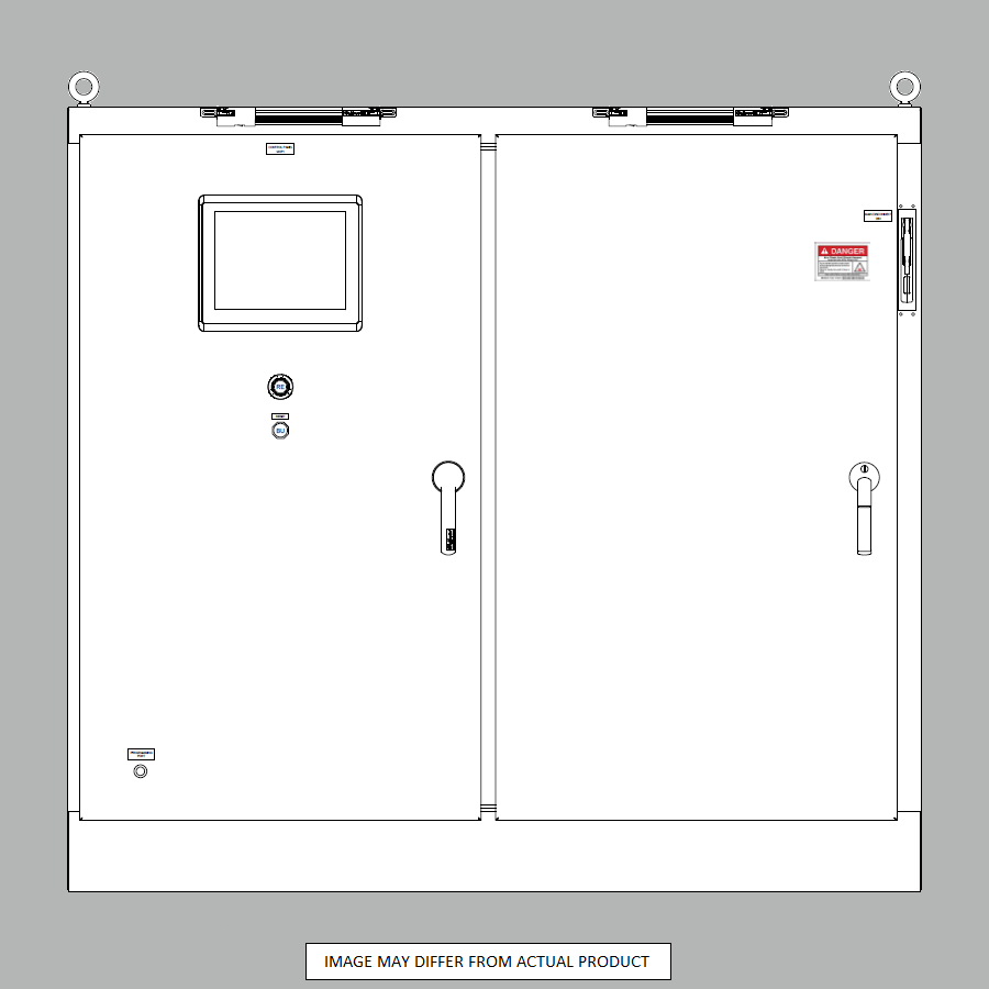
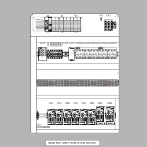
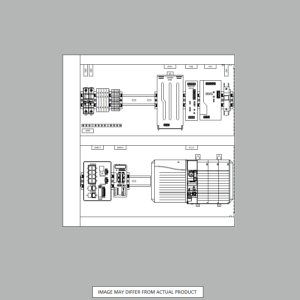
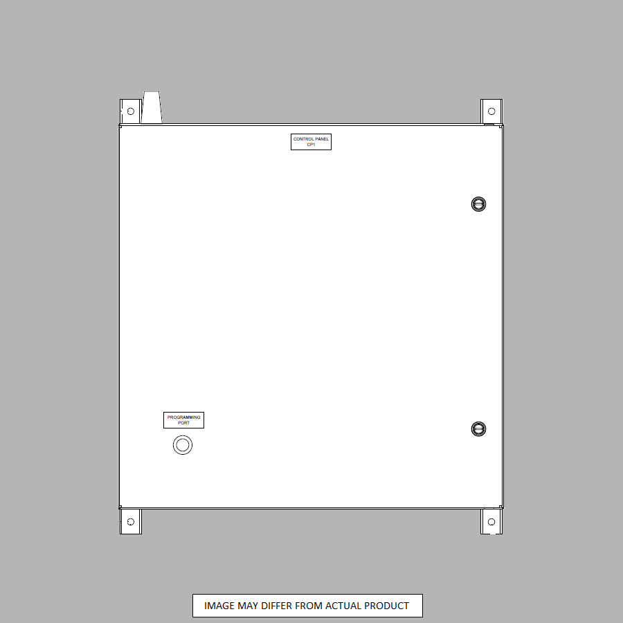
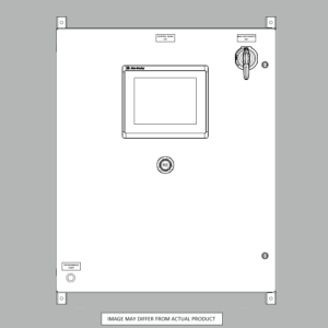
At Automation Ready Panels, we use diagrams like a. hardware block diagram in our PLC control panel work. Contact us for any of your PLC control panel needs or automation requirements.
-

Large Process Automation: Panelview 5000, ControlLogix 5580
$28,997.00 Select options -
Small Process Automation: Panelview 5000, ControlLogix 5580
$24,011.00 Select options -
Small Process Automation: ControlLogix 5580, UPS Battery Backup, Cellular Modem
$20,089.00 Select options -
Advanced Automation: Panelview 5000, Safety CompactLogix 5380
$12,547.00 Select options