Equipment Modules (EM01, EM02…)
|
|
|
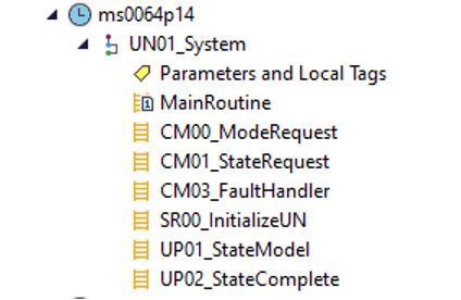
This program is written using ISA 88 techniques. An equipment module controls a logically separated modular part of the system that does its own function (like pump/tank that work together. If there were 4 identical pump/tanks, these would be each be equipment modules. The entire system of all 4 tanks/pumps working together as a unit would be called a Unit Module). These functions should be identified before trying to program the PLC using this technique. The equipment modules get called from the Unit Module (UN01). This unit module is considered the automatic routine for the entire system. It coordinates the equipment modules to run in a certain order or together. This level of the logic does not need to be modified, only the equipment modules. See the Rockwell Automation Machine Builder Library documentation for more details.
Note – Programmer should read programming notes stored in the PLC READ_ME program. They should rename any tags, programs, routines, equipment, or unit modules to be more specific to the application.
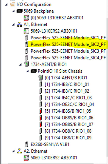
Start by adding any IO modules or devices to the IO tree needed by each equipment module.
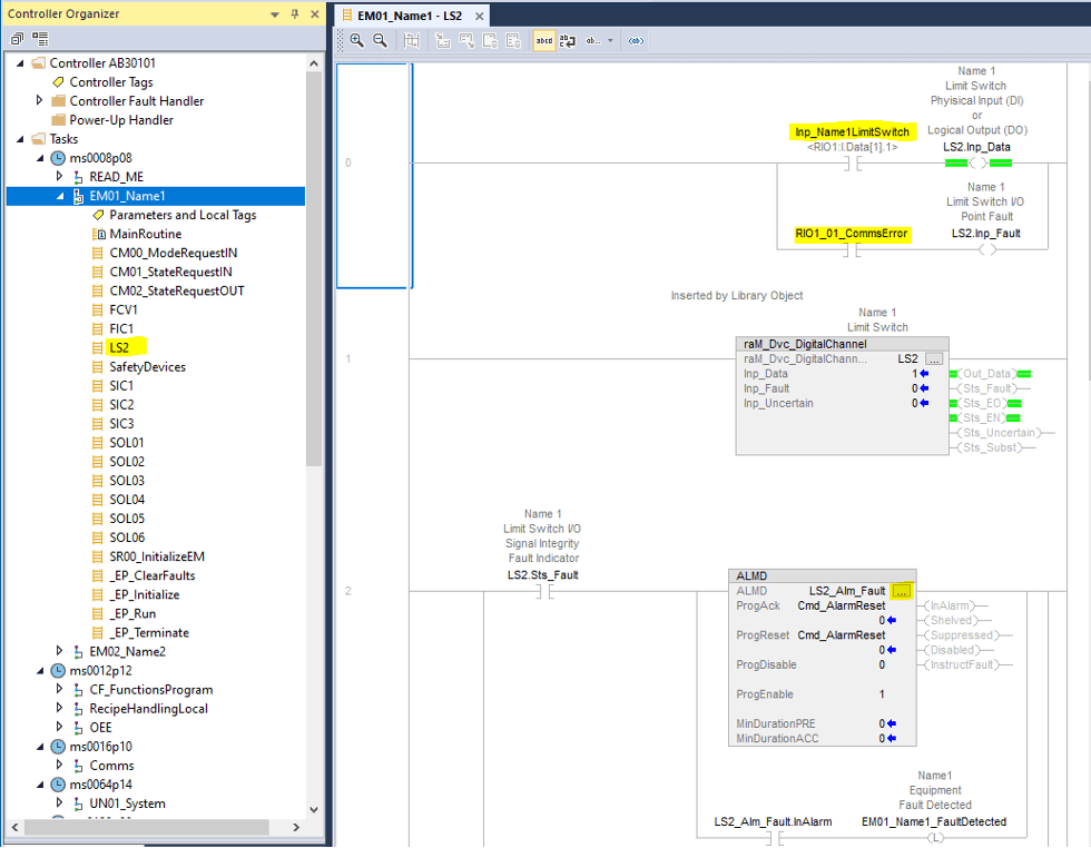
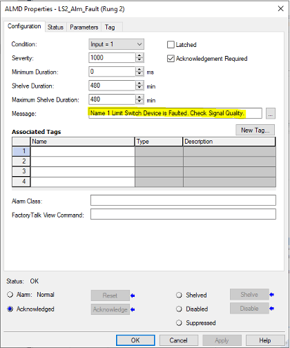
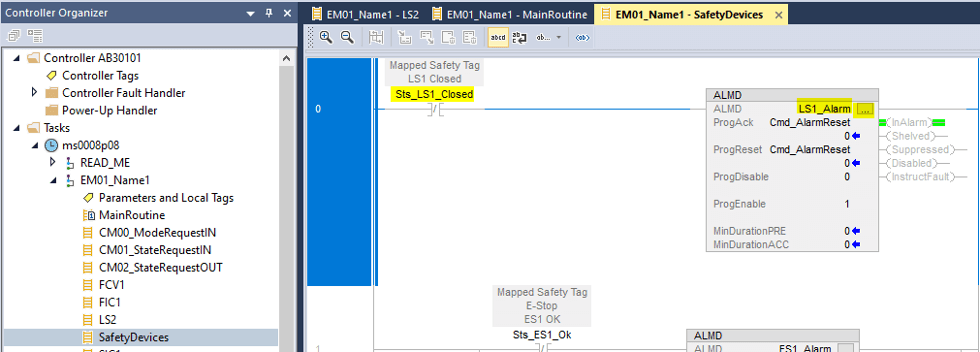
Next, install the device routines associated with this equipment module (LS2 for example). Each type of device will have unique programming blocks and logic. Choosing the right blocks and logic is very important. In the example below, a discrete input limit switch was programmed for this equipment module. The logic includes the Machine Builder programming block, any device alarms, and the raw module input tag. There is also a tag to fault the device if the IO module that drives the device ever faults (see section 4.6). Change any tag names to suit. Remember to click on the ellipse of the ALDM block to fill out the alarm message shown below. Alarm messages show up on the HMI when they are triggered.
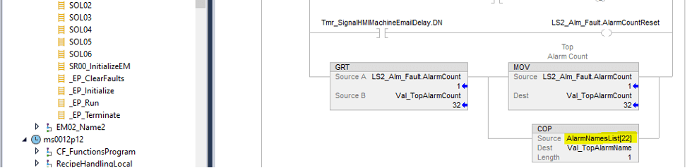
Also ensure the string for this alarm is filled out as shown below. This string is used to track top 5 alarms every month.
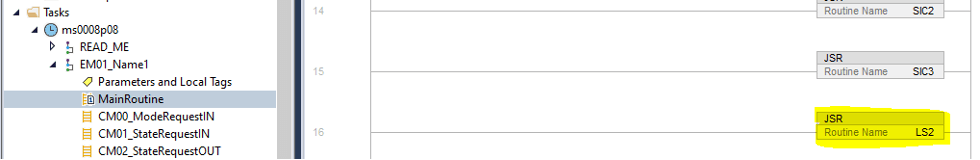
Add the newly created routine to the MainRoutine so that it gets scanned.
Any ALMD alarms associated with the SafetyProgram logic should be added to the SafetyDevices routine. Be sure to click on the ellipse and fill out the alarm message as mentioned above.
Now the equipment module automatic logic should be written. There are 4 routines that could require logic, depending on the automation application. The first routine is the Clear Faults routine. This routine runs when the equipment module is reset from a fault condition. Reset equipment devices in this routine if needed as shown below. More sequence steps can be added if necessary, for sequential equipment resets.
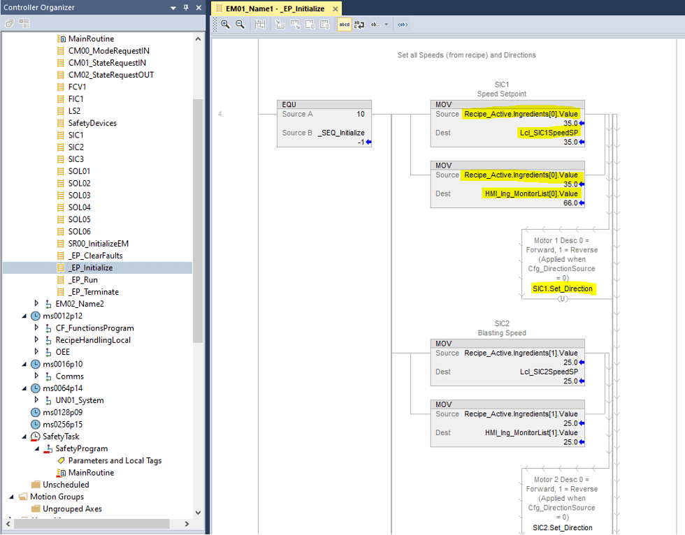
Next is the Initialize routine. This routine is used to set up equipment devices and settings before the system turns into automatic sequencing. This is the routine should be used to place recipe settings into the tags that drive the equipment in the automatic sequencer. This routine also includes a sequencer in case setup or homing of equipment needs to happen.
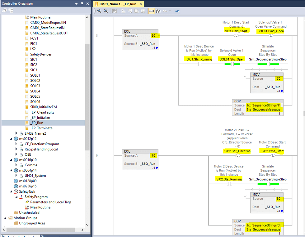
The third routine is the Run routine. This routine runs after the initialize routine runs. This is the main sequencer for this equipment module ONLY. This system will remain in this run routine in automatic mode until the sequencer finishes, faults, or is stopped.
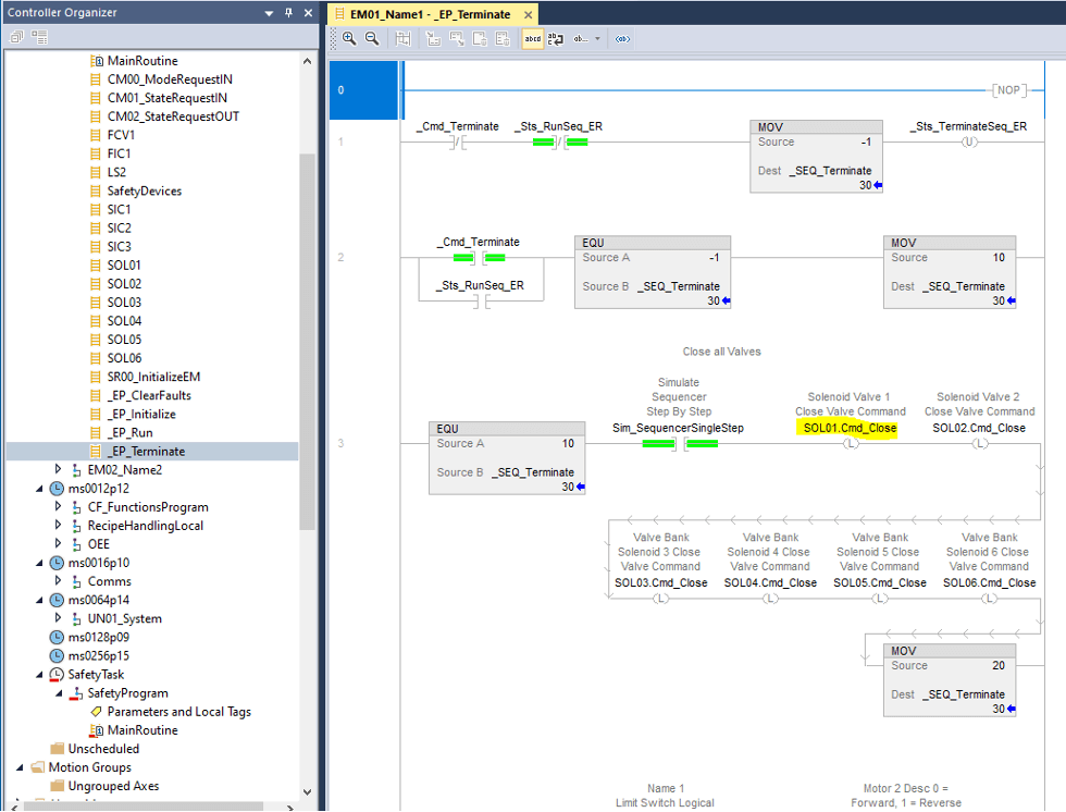
The fourth and final routine is the Terminate routine. This routine runs after an equipment module fault, the run sequencer finishes, or the equipment module is stopped. Any equipment that needs to be shut off should be placed in this routine, as shown below.
Note – As a reminder, this logic above applies only to one “tank/pump” equipment, not the whole system. The next equipment routine should now be written for the next subcomponent equipment for the system.
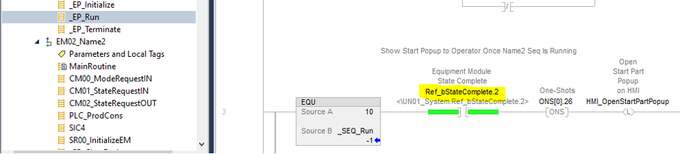
If the application is such that certain equipment modules must wait for others to get running, a bit can be added at the beginning of the second-in-line equipment module, forcing it to wait. See below for what bit should be used.
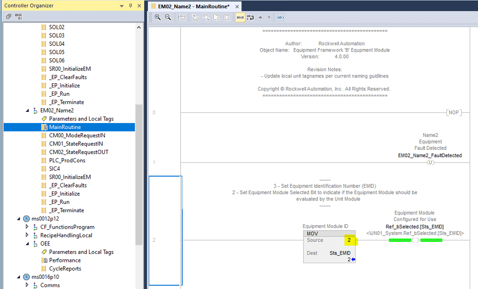
The Ref_bStateComplete.2 bit shown above is from the EM02 module. Each module has a unique number that corresponds to that equipment module. This number can be found as shown below. When new equipment modules are created, a unique number must be assigned to match the new equipment module.
|